WebGPU Loading Images into Textures
This article is one in a series of the various ways to provide data to a shader. Each one builds on the previous lesson so you may find them easiest to understand by reading them in order.
- Inter-stage Variables
- Uniforms
- Storage Buffers
- Vertex Buffers
- Textures
- Loading Images ⬅ You are here
- Using Video
- Cube Maps
- Storage Textures
- Multisampling / MSAA
- Immediates
- Constants
- Miscellaneous Shader Input
We covered some basics about using textures in the previous article. In this article we’ll cover loading an image into a texture as well as generating mipmaps on the GPU.
In the previous article we’d created a texture by calling device.createTexture and then
put data in the texture by calling device.queue.writeTexture. There’s another function
on device.queue called device.queue.copyExternalImageToTexture that let’s us copy
an image into a texture.
It can take an ImageBitmap so let’s take the magFilter example from the previous article and change it to load a few images.
First we need some code to get an ImageBitmap from an image
  async function loadImageBitmap(url) {
    const res = await fetch(url);
    const blob = await res.blob();
    return await createImageBitmap(blob, { colorSpaceConversion: 'none' });
  }
The code above calls fetch with the url of an image. This returns a Response. We then
use that to load a Blob which opaquely represents the data of the image file. We then pass
that to createImageBitmap which is a standard browser function to create an ImageBitmap.
We pass { colorSpaceConversion: 'none' } to tell the browser not to apply any color space. It’s up to you if
you want the browser to apply a color space or not. Often in WebGPU we might load
an image that is a normal map or a height map or something that is not color data.
In those cases we definitely don’t want the browser to muck with the data in the image.
Now that we have code to create an ImageBitmap let’s load one and create a texture of the same size.
We’ll load this image

I was taught once that a texture with an F in it is a good example texture because we can instantly
see its orientation.

-  const texture = device.createTexture({
-    label: 'yellow F on red',
-    size: [kTextureWidth, kTextureHeight],
-    format: 'rgba8unorm',
-    usage:
-      GPUTextureUsage.TEXTURE_BINDING |
-      GPUTextureUsage.COPY_DST,
-  });
+  const url = 'resources/images/f-texture.png';
+  const source = await loadImageBitmap(url);
+  const texture = device.createTexture({
+    label: url,
+    format: 'rgba8unorm',
+    size: [source.width, source.height],
+    usage: GPUTextureUsage.TEXTURE_BINDING |
+           GPUTextureUsage.COPY_DST |
+           GPUTextureUsage.RENDER_ATTACHMENT,
+  });
Note that copyExternalImageToTexture requires that we include to
GPUTextureUsage.COPY_DST and GPUTextureUsage.RENDER_ATTACHMENT
usage flags.
So then we can copy the ImageBitmap to the texture
-  device.queue.writeTexture(
-      { texture },
-      textureData,
-      { bytesPerRow: kTextureWidth * 4 },
-      { width: kTextureWidth, height: kTextureHeight },
-  );
+  device.queue.copyExternalImageToTexture(
+    { source, flipY: true },
+    { texture },
+    { width: source.width, height: source.height },
+  );
The parameters to copyExternalImageToTexture are
The source, the destination, the size. For the source
we can specify flipY: true if we want the texture flipped on load.
And that works!
Generating mips on the GPU
In the previous article we also generated a mipmap
but in that case we had easy access to the image data. When loading an image, we
could draw that image into a 2D canvas, the call getImageData to get the data, and
finally generate mips and upload. That would be pretty slow. It would also potentially
be lossy since how canvas 2D renders is intentionally implementation dependant.
When we generated mip levels we did a bilinear interpolation which is exactly what
the GPU does with minFilter: linear. We can use that feature to generate mip levels
on the GPU
Let’s modify the mipmapFilter example from the previous article to load images and generate mips using the GPU
First, let’s change the code that creates the texture to create mip levels. We need to know how many to create which we can calculate like this
  const numMipLevels = (...sizes) => {
    const maxSize = Math.max(...sizes);
    return 1 + Math.log2(maxSize) | 0;
  };
We can call that with 1 or more numbers and it will return the number of mips needed, so for example
numMipLevels(123, 456) returns 9.
- level 0: 123, 456
- level 1: 61, 228
- level 2: 30, 114
- level 3: 15, 57
- level 4: 7, 28
- level 5: 3, 14
- level 6: 1, 7
- level 7: 1, 3
- level 8: 1, 1
9 mip levels
Math.log2 tells us the power of 2 we need to make our number.
In other words, Math.log2(8) = 3 because 23 = 8. Another way to say the same thing is, Math.log2 tells us how
many times can we divide this number by 2.
Math.log2(8)
          8 / 2 = 4
                  4 / 2 = 2
                          2 / 2 = 1
So we can divide 8 by 2 three times. That’s exactly what we need to compute how many mip levels to make.
It’s Math.log2(largestSize) + 1. 1 for the original size mip level 0
So, we can now create the right number of mip levels
  const texture = device.createTexture({
    label: url,
    format: 'rgba8unorm',
    mipLevelCount: numMipLevels(source.width, source.height),
    size: [source.width, source.height],
    usage: GPUTextureUsage.TEXTURE_BINDING |
           GPUTextureUsage.COPY_DST |
           GPUTextureUsage.RENDER_ATTACHMENT,
  });
  device.queue.copyExternalImageToTexture(
    { source, flipY: true, },
    { texture },
    { width: source.width, height: source.height },
  );
To generate the next mip level, we’ll draw a textured quad, just like we’ve been doing, from the
existing mip level, to the next level, with minFilter: linear.
Here’s the code
  const generateMips = (() => {
    let sampler;
    let module;
    const pipelineByFormat = {};

    return function generateMips(device, texture) {
      if (!module) {
        module = device.createShaderModule({
          label: 'textured quad shaders for mip level generation',
          code: /* wgsl */ `
            struct VSOutput {
              @builtin(position) position: vec4f,
              @location(0) texcoord: vec2f,
            };

            @vertex fn vs(
              @builtin(vertex_index) vertexIndex : u32
            ) -> VSOutput {
              let pos = array(
                // 1st triangle
                vec2f( 0.0,  0.0),  // center
                vec2f( 1.0,  0.0),  // right, center
                vec2f( 0.0,  1.0),  // center, top

                // 2nd triangle
                vec2f( 0.0,  1.0),  // center, top
                vec2f( 1.0,  0.0),  // right, center
                vec2f( 1.0,  1.0),  // right, top
              );

              var vsOutput: VSOutput;
              let xy = pos[vertexIndex];
              vsOutput.position = vec4f(xy * 2.0 - 1.0, 0.0, 1.0);
              vsOutput.texcoord = vec2f(xy.x, 1.0 - xy.y);
              return vsOutput;
            }

            @group(0) @binding(0) var ourSampler: sampler;
            @group(0) @binding(1) var ourTexture: texture_2d<f32>;

            @fragment fn fs(fsInput: VSOutput) -> @location(0) vec4f {
              return textureSample(ourTexture, ourSampler, fsInput.texcoord);
            }
          `,
        });

        sampler = device.createSampler({
          minFilter: 'linear',
        });
      }

      if (!pipelineByFormat[texture.format]) {
        pipelineByFormat[texture.format] = device.createRenderPipeline({
          label: 'mip level generator pipeline',
          layout: 'auto',
          vertex: {
            module,
          },
          fragment: {
            module,
            targets: [{ format: texture.format }],
          },
        });
      }
      const pipeline = pipelineByFormat[texture.format];

      const encoder = device.createCommandEncoder({
        label: 'mip gen encoder',
      });

      for (let baseMipLevel = 1; baseMipLevel < texture.mipLevelCount; ++baseMipLevel) {
        const bindGroup = device.createBindGroup({
          layout: pipeline.getBindGroupLayout(0),
          entries: [
            { binding: 0, resource: sampler },
            {
              binding: 1,
              resource: texture.createView({
                baseMipLevel: baseMipLevel - 1,
                mipLevelCount: 1,
              }),
            },
          ],
        });

        const renderPassDescriptor = {
          label: 'our basic canvas renderPass',
          colorAttachments: [
            {
              view: texture.createView({
                baseMipLevel,
                mipLevelCount: 1,
              }),
              loadOp: 'clear',
              storeOp: 'store',
            },
          ],
        };

        const pass = encoder.beginRenderPass(renderPassDescriptor);
        pass.setPipeline(pipeline);
        pass.setBindGroup(0, bindGroup);
        pass.draw(6);  // call our vertex shader 6 times
        pass.end();
      }
      const commandBuffer = encoder.finish();
      device.queue.submit([commandBuffer]);
    };
  })();
The code above looks long but it’s almost the exact same code we’ve been using in our examples with textures so far. What’s changed
-
We make a closure to hold on to 3 variables.
module,sampler,pipelineByFormat. Formoduleandsamplerwe check if they have not be set and if not, we create aGPUSShaderModuleandGPUSamplerwhich we can hold on to and use in the future. -
We have a pair of shaders that are almost exactly the same as all the examples so far. The only difference is this part
-  vsOutput.position = uni.matrix * vec4f(xy, 0.0, 1.0);
-  vsOutput.texcoord = xy * vec2f(1, 50);
+  vsOutput.position = vec4f(xy * 2.0 - 1.0, 0.0, 1.0);
+  vsOutput.texcoord = vec2f(xy.x, 1.0 - xy.y);
The hard coded quad position data we have in shader goes from 0.0 to 1.0 and so, as is, would only cover the top right quarter texture we’re drawing to, just as it does in the examples. We need it to cover the entire area so by multiplying by 2 and subtracting 1 we get a quad that goes from -1,-1 to +1,+1.
We also flip the Y texture coordinate. This is because when drawing to the texture +1, +1 is at the top right but we want the top right of the texture we are sampling to be there. The top right of the sampled texture is +1, 0
-
We have an object,
pipelineByFormatwhich we use as a map of pipelines to texture formats. This is because a pipeline needs to know the format to use. -
We check if we already have a pipeline for a particular format and if not create one
    if (!pipelineByFormat[texture.format]) {
      pipelineByFormat[texture.format] = device.createRenderPipeline({
        label: 'mip level generator pipeline',
        layout: 'auto',
        vertex: {
          module,
        },
        fragment: {
          module,
+          targets: [{ format: texture.format }],
        },
      });
    }
    const pipeline = pipelineByFormat[texture.format];
The only major difference here is
targetsis set from the texture’s format, not from thepresentationFormatwe use when rendering to the canvas -
We finally use some parameters to
texture.createViewThis is the first time we’ve used
createViewwhen binding a texture to a bind group, and when setting a texture as a colorTarget. When you bind a texture in to a bind group, or when you assign a texture as a render target (settingcolorTargets), you can either pass a texture directly, or you can pass aGPUTextureView.{ binding: resource: someTexture },and
{ binding: resource: someTexture.createView(...) },Using the texture directly is effectively a shortcut for calling
texture.createViewwith no parameters. With no parameters it means you want to access the entire texture. With parameters,createViewlets you select a subset of the texture. In this case we usecreateViewto select the mip level we want to read from. We set this in the bindGroup. And, we usecreateViewagain, to select which mip level we want to render to in the render pass descriptor.We loop over each mip level that we need to generate. We create a bind group for the last mip with data in it and we set the renderPassDescriptor to draw to the current mip level. Then we encode a renderPass for that specific mip level. When we’re done. All the mips will have been filled out.
    for (let baseMipLevel = 1; baseMipLevel < texture.mipLevelCount; ++baseMipLevel) {
      const bindGroup = device.createBindGroup({
        layout: pipeline.getBindGroupLayout(0),
        entries: [
          { binding: 0, resource: sampler },
+          {
+            binding: 1,
+            resource: texture.createView({
+              baseMipLevel: baseMipLevel - 1,
+              mipLevelCount: 1,
+            }),
+          },
        ],
      });

      const renderPassDescriptor = {
        label: 'our basic canvas renderPass',
        colorAttachments: [
          {
+            view: texture.createView({baseMipLevel, mipLevelCount: 1}),
            loadOp: 'clear',
            storeOp: 'store',
          },
        ],
      };

      const pass = encoder.beginRenderPass(renderPassDescriptor);
      pass.setPipeline(pipeline);
      pass.setBindGroup(0, bindGroup);
      pass.draw(6);  // call our vertex shader 6 times
      pass.end();
    }

    const commandBuffer = encoder.finish();
    device.queue.submit([commandBuffer]);
Note: This function only handles 2d textures. The article on cubemaps covers how to expand this function to handle 2d-array textures and cube maps.
Simple Image Loading Functions
Let’s create some support functions make it simple load an image into a texture and generate mips
Here’s a function that updates the first mip level and optionally flips the image. If the image has mip levels then we generate them.
  function copySourceToTexture(device, texture, source, {flipY} = {}) {
    device.queue.copyExternalImageToTexture(
      { source, flipY, },
      { texture },
      { width: source.width, height: source.height },
    );

    if (texture.mipLevelCount > 1) {
      generateMips(device, texture);
    }
  }
Here’s a function that given a source (in this case an ImageBitmap) will
create a texture of the matching size and then call the previous function
to fill it in with the data
  function createTextureFromSource(device, source, options = {}) {
    const texture = device.createTexture({
      format: 'rgba8unorm',
*      mipLevelCount: options.mips ? numMipLevels(source.width, source.height) : 1,
      size: [source.width, source.height],
      usage: GPUTextureUsage.TEXTURE_BINDING |
             GPUTextureUsage.COPY_DST |
             GPUTextureUsage.RENDER_ATTACHMENT,
    });
    copySourceToTexture(device, texture, source, options);
    return texture;
  }
and here’s a function that given a url will load the url as an ImageBitmap call
call the previous function to create a texture and fill it with the contents of the image.
  async function createTextureFromImage(device, url, options) {
    const imgBitmap = await loadImageBitmap(url);
    return createTextureFromSource(device, imgBitmap, options);
  }
With those setup, the only major change to the mipmapFilter sample is this
- const textures = [
- createTextureWithMips(createBlendedMipmap(), 'blended'),
- createTextureWithMips(createCheckedMipmap(), 'checker'),
- ];
+ const textures = await Promise.all([
+ await createTextureFromImage(device,
+ 'resources/images/f-texture.png', {mips: true, flipY: false}),
+ await createTextureFromImage(device,
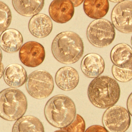
+ 'resources/images/coins.jpg', {mips: true}),
+ await createTextureFromImage(device,
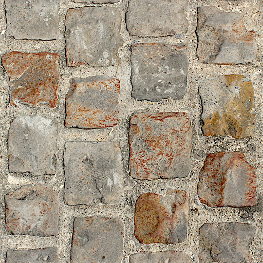
+ 'resources/images/Granite_paving_tileable_512x512.jpeg', {mips: true}),
+ ]);
The code above loads the F texture from above as well as these 2 tiling textures
And here it is
Loading Canvas
copyExternalImageToTexture takes other sources. Another is an HTMLCanvasElement.
We can use this to draw things in a 2d canvas, and then get the result in a texture in WebGPU.
Of course you can use WebGPU to draw to a texture and use that texture you just drew to
in something else you render. In fact we just did that, rendering to a mip level and then
using that mip level a texture attachment to render to the next mip level.
But, sometimes using 2d canvas can make certain things easy. The 2d canvas has relatively high level API.
So, first let’s make some kind of canvas animation.
const size = 256;
const half = size / 2;

const ctx = document.createElement('canvas').getContext('2d');
ctx.canvas.width = size;
ctx.canvas.height = size;

const hsl = (h, s, l) => `hsl(${h * 360 | 0}, ${s * 100}%, ${l * 100 | 0}%)`;

function update2DCanvas(time) {
  time *= 0.0001;
  ctx.clearRect(0, 0, size, size);
  ctx.save();
  ctx.translate(half, half);
  const num = 20;
  for (let i = 0; i < num; ++i) {
    ctx.fillStyle = hsl(i / num * 0.2 + time * 0.1, 1, i % 2 * 0.5);
    ctx.fillRect(-half, -half, size, size);
    ctx.rotate(time * 0.5);
    ctx.scale(0.85, 0.85);
    ctx.translate(size / 16, 0);
  }
  ctx.restore();
}

function render(time) {
  update2DCanvas(time);
  requestAnimationFrame(render);
}
requestAnimationFrame(render);
To load that canvas into WebGPU only a few changes are needed to our previous example.
We need to create a texture of the right size. The easiest way it just to use the same code we wrote above
+  const texture = createTextureFromSource(device, ctx.canvas, {mips: true});

  const textures = await Promise.all([
-    await createTextureFromImage(device,
-        'resources/images/f-texture.png', {mips: true, flipY: false}),
-    await createTextureFromImage(device,
-        'resources/images/coins.jpg', {mips: true}),
-    await createTextureFromImage(device,
-        'resources/images/Granite_paving_tileable_512x512.jpeg', {mips: true}),
+    texture,
  ]);
Then we need to switch to a requestAnimationFrame loop, update the 2D canvas, and
then upload it to WebGPU
-  function render() {
+  function render(time) {
+    update2DCanvas(time);
+    copySourceToTexture(device, texture, ctx.canvas);

     ...


    requestAnimationFrame(render);
  }
  requestAnimationFrame(render);

  const observer = new ResizeObserver(entries => {
    for (const entry of entries) {
      const canvas = entry.target;
      const width = entry.contentBoxSize[0].inlineSize;
      const height = entry.contentBoxSize[0].blockSize;
      canvas.width = Math.max(1, Math.min(width, device.limits.maxTextureDimension2D));
      canvas.height = Math.max(1, Math.min(height, device.limits.maxTextureDimension2D));
-      render();
    }
  });
  observer.observe(canvas);

  canvas.addEventListener('click', () => {
    texNdx = (texNdx + 1) % textures.length;
-    render();
  });
With that we’re able to upload a canvas AND generate mips levels for it
Loading Video
Loading video this way is no different. We can create a <video> element and pass
it to the same functions we passed the canvas to in the previous example and it should
just work with minor adjustments
Here’s a video
ImageBitmap and HTMLCanvasElement have their width and height as width and height properties but HTMLVideoElement has its width and height
on videoWidth and videoHeight. So, let’s update the code to handle that difference
+  function getSourceSize(source) {
+    return [
+      source.videoWidth || source.width,
+      source.videoHeight || source.height,
+    ];
+  }

  function copySourceToTexture(device, texture, source, {flipY} = {}) {
    device.queue.copyExternalImageToTexture(
      { source, flipY, },
      { texture },
-      { width: source.width, height: source.height },
+      getSourceSize(source),
    );

    if (texture.mipLevelCount > 1) {
      generateMips(device, texture);
    }
  }

  function createTextureFromSource(device, source, options = {}) {
+    const size = getSourceSize(source);
    const texture = device.createTexture({
      format: 'rgba8unorm',
-      mipLevelCount: options.mips ? numMipLevels(source.width, source.height) : 1,
-      size: [source.width, source.height],
+      mipLevelCount: options.mips ? numMipLevels(...size) : 1,
+      size,
      usage: GPUTextureUsage.TEXTURE_BINDING |
             GPUTextureUsage.COPY_DST |
             GPUTextureUsage.RENDER_ATTACHMENT,
    });
    copySourceToTexture(device, texture, source, options);
    return texture;
  }
So then, lets setup a video element
  const video = document.createElement('video');
  video.muted = true;
  video.loop = true;
  video.preload = 'auto';
  video.src = 'resources/videos/Golden_retriever_swimming_the_doggy_paddle-360-no-audio.webm';

  const texture = createTextureFromSource(device, video, {mips: true});
and update it at render time
-  function render(time) {
-    update2DCanvas(time);
-    copySourceToTexture(device, texture, ctx.canvas);
+  function render() {
+    copySourceToTexture(device, texture, video);
One complication of videos is we need to wait for them to have started
playing before we pass them to WebGPU. In modern browsers we can do
this by calling video.requestVideoFrameCallback. It calls us each time
a new frame is available so we can use it to find out when at least
one frame is available.
For a fallback, we can wait for the time to advance and pray 🙏 because sadly, old browsers made it hard to know when it’s safe to use a video 😅
+  function startPlayingAndWaitForVideo(video) {
+    return new Promise((resolve, reject) => {
+      video.addEventListener('error', reject);
+      if ('requestVideoFrameCallback' in video) {
+        video.requestVideoFrameCallback(resolve);
+      } else {
+        const timeWatcher = () => {
+          if (video.currentTime > 0) {
+            resolve();
+          } else {
+            requestAnimationFrame(timeWatcher);
+          }
+        };
+        timeWatcher();
+      }
+      video.play().catch(reject);
+    });
+  }

  const video = document.createElement('video');
  video.muted = true;
  video.loop = true;
  video.preload = 'auto';
  video.src = 'resources/videos/Golden_retriever_swimming_the_doggy_paddle-360-no-audio.webm';
+  await startPlayingAndWaitForVideo(video);

  const texture = createTextureFromSource(device, video, {mips: true});
Another complication is we need to wait for the user to interact with the page before we can start the video [1]. Let’s add some HTML with a play button.
  <body>
    <canvas></canvas>
+    <div id="start">
+      <div>▶️</div>
+    </div>
  </body>
And some CSS to center it
#start {
  position: fixed;
  left: 0;
  top: 0;
  width: 100%;
  height: 100%;
  display: flex;
  justify-content: center;
  align-items: center;
}
#start>div {
  font-size: 200px;
  cursor: pointer;
}
Then let’s write a function to wait for it to be clicked and hide it.
+  function waitForClick() {
+    return new Promise(resolve => {
+      window.addEventListener(
+        'click',
+        () => {
+          document.querySelector('#start').style.display = 'none';
+          resolve();
+        },
+        { once: true });
+    });
+  }

  const video = document.createElement('video');
  video.muted = true;
  video.loop = true;
  video.preload = 'auto';
  video.src = 'resources/videos/Golden_retriever_swimming_the_doggy_paddle-360-no-audio.webm';
+  await waitForClick();
  await startPlayingAndWaitForVideo(video);

  const texture = createTextureFromSource(device, video, {mips: true});
Let’s also add a wait to pause the video
  const video = document.createElement('video');
  video.muted = true;
  video.loop = true;
  video.preload = 'auto';
  video.src = 'resources/videos/pexels-anna-bondarenko-5534310 (540p).mp4'; /* webgpufundamentals: url */
  await waitForClick();
  await startPlayingAndWaitForVideo(video);

+  canvas.addEventListener('click', () => {
+    if (video.paused) {
+      video.play();
+    } else {
+      video.pause();
+    }
+  });
And with that we should get video in a texture
One optimization we could make. We could only update the texture when the video has changed.
For example
  const video = document.createElement('video');
  video.muted = true;
  video.loop = true;
  video.preload = 'auto';
  video.src = 'resources/videos/Golden_retriever_swimming_the_doggy_paddle-360-no-audio.webm';
  await waitForClick();
  await startPlayingAndWaitForVideo(video);

+  let alwaysUpdateVideo = !('requestVideoFrameCallback' in video);
+  let haveNewVideoFrame = false;
+  if (!alwaysUpdateVideo) {
+    function recordHaveNewFrame() {
+      haveNewVideoFrame = true;
+      video.requestVideoFrameCallback(recordHaveNewFrame);
+    }
+    video.requestVideoFrameCallback(recordHaveNewFrame);
+  }

  ...

  function render() {
+    if (alwaysUpdateVideo || haveNewVideoFrame) {
+      haveNewVideoFrame = false;
      copySourceToTexture(device, texture, video);
+    }

    ...
With this change we’d only update the video for each new frame. So, for example, on a device with a display rate of 120 frames per second we’d draw at 120 frames per second so animations, camera movements, etc would be smooth. But, the video texture itself would only update at its own frame rate (for example 30fps).
BUT! WebGPU has special support for using video efficiently
We’ll cover that in another article.
The way above, using device.query.copyExternalImageToTexture is actually
making a copy. Making a copy takes time. For example a 4k video’s resolution
is generally 3840 × 2160 which for rgba8unorm is 31meg of data that needs to be
copied, per frame. External textures
let you use the video’s data directly (no copy) but require different methods
and have some restrictions.
Texture Atlases
From the examples above, we can see that to draw something with a texture we have to create the texture, put data it in, bind it to bindGroup with a sampler, and reference it from a shader. So what would we do if we wanted to draw multiple different textures on an object? Say we had a chair where the legs and back are made of wood but the cushion is made of cloth.
Or a car where the tires are rubber, the body is paint, the bumpers and hub caps are chrome.
If we did nothing else you might think we’d have to draw 2 times for the chair, once for the wood with a wood texture, and once for the cushion with a cloth texture. For the car we’d have several draws, one for the tires, one for the body, one for the bumpers, etc…
That would end up being slow as every object would require multiple draw calls. We could try to fix that by adding more inputs to our shader (2, 3, 4 textures) with texture coordinates for each one but that would not be very flexible and would be slow as well as we’d need to read all 4 textures and add code to chose between them.
The most common way to cover this case is to use what’s called a Texture Atlas. A Texture Atlas is a fancy name for a texture with multiple images it in. We then use texture coordinates to select which parts go where.
Let’s wrap a cube with these 6 images
 |  |
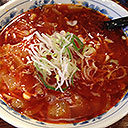 | 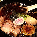 |
 |  |
Using some image editing software like Photoshop or Photopea we could put all 6 images into a single image
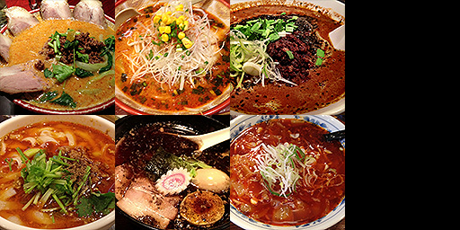
We’d then make a cube and provide texture coordinates that select each portion of the image onto a specific face of the cube. To keep it simple I put all 6 images in the texture above in squares, 4x2. So it should be pretty easy to compute the texture coordinates for each square.
The diagram above might be confusing because it is often suggested that texture coordinates have 0,0 as the bottom left corner. Really though there is no “bottom”. There is just the idea that texture coordinate 0,0 references the first pixel in the texture’s data. The first pixel in the texture’s data is the top left corner of the image. If you subscribe to the idea that 0,0 = bottom left then our texture coordinates would be visualized like this. They’re still the same coordinates.
Here’s the position vertices for a cube and the texture coordinates to go with them
function createCubeVertices() {
  const vertexData = new Float32Array([
     //  position   |  texture coordinate
     //-------------+----------------------
     // front face     select the top left image
    -1,  1,  1,        0   , 0  ,
    -1, -1,  1,        0   , 0.5,
     1,  1,  1,        0.25, 0  ,
     1, -1,  1,        0.25, 0.5,
     // right face     select the top middle image
     1,  1, -1,        0.25, 0  ,
     1,  1,  1,        0.5 , 0  ,
     1, -1, -1,        0.25, 0.5,
     1, -1,  1,        0.5 , 0.5,
     // back face      select to top right image
     1,  1, -1,        0.5 , 0  ,
     1, -1, -1,        0.5 , 0.5,
    -1,  1, -1,        0.75, 0  ,
    -1, -1, -1,        0.75, 0.5,
    // left face       select the bottom left image
    -1,  1,  1,        0   , 0.5,
    -1,  1, -1,        0.25, 0.5,
    -1, -1,  1,        0   , 1  ,
    -1, -1, -1,        0.25, 1  ,
    // bottom face     select the bottom middle image
     1, -1,  1,        0.25, 0.5,
    -1, -1,  1,        0.5 , 0.5,
     1, -1, -1,        0.25, 1  ,
    -1, -1, -1,        0.5 , 1  ,
    // top face        select the bottom right image
    -1,  1,  1,        0.5 , 0.5,
     1,  1,  1,        0.75, 0.5,
    -1,  1, -1,        0.5 , 1  ,
     1,  1, -1,        0.75, 1  ,

  ]);

  const indexData = new Uint16Array([
     0,  1,  2,  2,  1,  3,  // front
     4,  5,  6,  6,  5,  7,  // right
     8,  9, 10, 10,  9, 11,  // back
    12, 13, 14, 14, 13, 15,  // left
    16, 17, 18, 18, 17, 19,  // bottom
    20, 21, 22, 22, 21, 23,  // top
  ]);

  return {
    vertexData,
    indexData,
    numVertices: indexData.length,
  };
}
To make this example we’re going to have start with an example from the article on cameras. If you haven’t read the article yet you can read it and the series it’s a part of the learn how do 3D. For now, the important part is, like we did above, we output positions and texture coordinates from our vertex shader and use them to look up values from a texture in our fragment shader. So, here’s the changes needed from the shader in the camera example, applying what we have above.
struct Uniforms {
  matrix: mat4x4f,
};

struct Vertex {
  @location(0) position: vec4f,
-  @location(1) color: vec4f,
+  @location(1) texcoord: vec2f,
};

struct VSOutput {
  @builtin(position) position: vec4f,
-  @location(0) color: vec4f,
+  @location(0) texcoord: vec2f,
};

@group(0) @binding(0) var<uniform> uni: Uniforms;
+@group(0) @binding(1) var ourSampler: sampler;
+@group(0) @binding(2) var ourTexture: texture_2d<f32>;

@vertex fn vs(vert: Vertex) -> VSOutput {
  var vsOut: VSOutput;
  vsOut.position = uni.matrix * vert.position;
-  vsOut.color = vert.color;
+  vsOut.texcoord = vert.texcoord;
  return vsOut;
}

@fragment fn fs(vsOut: VSOutput) -> @location(0) vec4f {
-  return vsOut.color;
+  return textureSample(ourTexture, ourSampler, vsOut.texcoord);
}
All we did was switch from taking a color per vertex to a texture coordinate per vertex and passing that texture coordinate to the fragment shader, like we did above. We then use it, in the fragment shader, like we did above.
In JavaScript we need to change that example’s pipeline from taking a color to taking texture coordinates
  const pipeline = device.createRenderPipeline({
    label: '2 attributes',
    layout: 'auto',
    vertex: {
      module,
      buffers: [
        {
-          arrayStride: (4) * 4, // (3) floats 4 bytes each + one 4 byte color
+          arrayStride: (3 + 2) * 4, // (3+2) floats 4 bytes each
          attributes: [
            {shaderLocation: 0, offset: 0, format: 'float32x3'},  // position
-            {shaderLocation: 1, offset: 12, format: 'unorm8x4'},  // color
+            {shaderLocation: 1, offset: 12, format: 'float32x2'},  // texcoord
          ],
        },
      ],
    },
    fragment: {
      module,
      targets: [{ format: presentationFormat }],
    },
    primitive: {
      cullMode: 'back',
    },
    depthStencil: {
      depthWriteEnabled: true,
      depthCompare: 'less',
      format: 'depth24plus',
    },
  });
To keep the data smaller we’re going to use indices like we covered in the article on vertex buffers.
-  const { vertexData, numVertices } = createFVertices();
+  const { vertexData, indexData, numVertices } = createCubeVertices();
  const vertexBuffer = device.createBuffer({
    label: 'vertex buffer vertices',
    size: vertexData.byteLength,
    usage: GPUBufferUsage.VERTEX | GPUBufferUsage.COPY_DST,
  });
  device.queue.writeBuffer(vertexBuffer, 0, vertexData);

+  const indexBuffer = device.createBuffer({
+    label: 'index buffer',
+    size: indexData.byteLength,
+    usage: GPUBufferUsage.INDEX | GPUBufferUsage.COPY_DST,
+  });
+  device.queue.writeBuffer(indexBuffer, 0, indexData);
We need to copy all of the texture loading and mip generation code into this example and then use it to load the texture atlas image. We also need to make a sampler and add them our bindGroup
+  const texture = await createTextureFromImage(device,
+      'resources/images/noodles.jpg', {mips: true, flipY: false});
+
+  const sampler = device.createSampler({
+    magFilter: 'linear',
+    minFilter: 'linear',
+    mipmapFilter: 'linear',
+  });

  const bindGroup = device.createBindGroup({
    label: 'bind group for object',
    layout: pipeline.getBindGroupLayout(0),
    entries: [
      { binding: 0, resource: uniformBuffer },
+      { binding: 1, resource: sampler },
+      { binding: 2, resource: texture },
    ],
  });
We need to do some 3D math to setup a matrix for drawing in 3D. (Again, see the camera article for details on 3D math.)
  const degToRad = d => d * Math.PI / 180;

  const settings = {
    rotation: [degToRad(20), degToRad(25), degToRad(0)],
  };

  const radToDegOptions = { min: -360, max: 360, step: 1, converters: GUI.converters.radToDeg };

  const gui = new GUI();
  gui.onChange(render);
  gui.add(settings.rotation, '0', radToDegOptions).name('rotation.x');
  gui.add(settings.rotation, '1', radToDegOptions).name('rotation.y');
  gui.add(settings.rotation, '2', radToDegOptions).name('rotation.z');

  ...

  function render() {

    ...

    const aspect = canvas.clientWidth / canvas.clientHeight;
    mat4.perspective(
        60 * Math.PI / 180,
        aspect,
        0.1,      // zNear
        10,      // zFar
        matrixValue,
    );
    const view = mat4.lookAt(
      [0, 1, 5],  // camera position
      [0, 0, 0],  // target
      [0, 1, 0],  // up
    );
    mat4.multiply(matrixValue, view, matrixValue);
    mat4.rotateX(matrixValue, settings.rotation[0], matrixValue);
    mat4.rotateY(matrixValue, settings.rotation[1], matrixValue);
    mat4.rotateZ(matrixValue, settings.rotation[2], matrixValue);

    // upload the uniform values to the uniform buffer
    device.queue.writeBuffer(uniformBuffer, 0, uniformValues);
And at render time we need to draw with indices
    const encoder = device.createCommandEncoder();
    const pass = encoder.beginRenderPass(renderPassDescriptor);
    pass.setPipeline(pipeline);
    pass.setVertexBuffer(0, vertexBuffer);
+    pass.setIndexBuffer(indexBuffer, 'uint16');

    ...

    pass.setBindGroup(0, bindGroup);
-    pass.draw(numVertices);
+    pass.drawIndexed(numVertices);

    pass.end();
And we get a cube, with a different image on each side, using a single texture.
Using a texture atlas is good because there’s just 1 texture to load, the shader stays simple as it only has to reference 1 texture, and it only requires 1 draw call to draw the shape instead of 1 draw call per texture as it might if we keep the images separate.
There are various ways to get a video, usually without audio, to autoplay without having to wait for the user to interact with the page. They seem to change over time so we won’t go into solutions here. ↩︎