WebGPU 컴퓨트 셰이더 - 이미지 히스토그램 Part 2
이전 문서에서 JavaScript로 이미지 히스토그램을 만드는 방법을 다루고 WebGPU를 사용하도록 변환한 다음 여러 단계의 최적화를 거쳤습니다.
몇 가지 더 해봅시다.
한 번에 4개의 히스토그램 생성하기
이런 이미지가 주어졌을 때
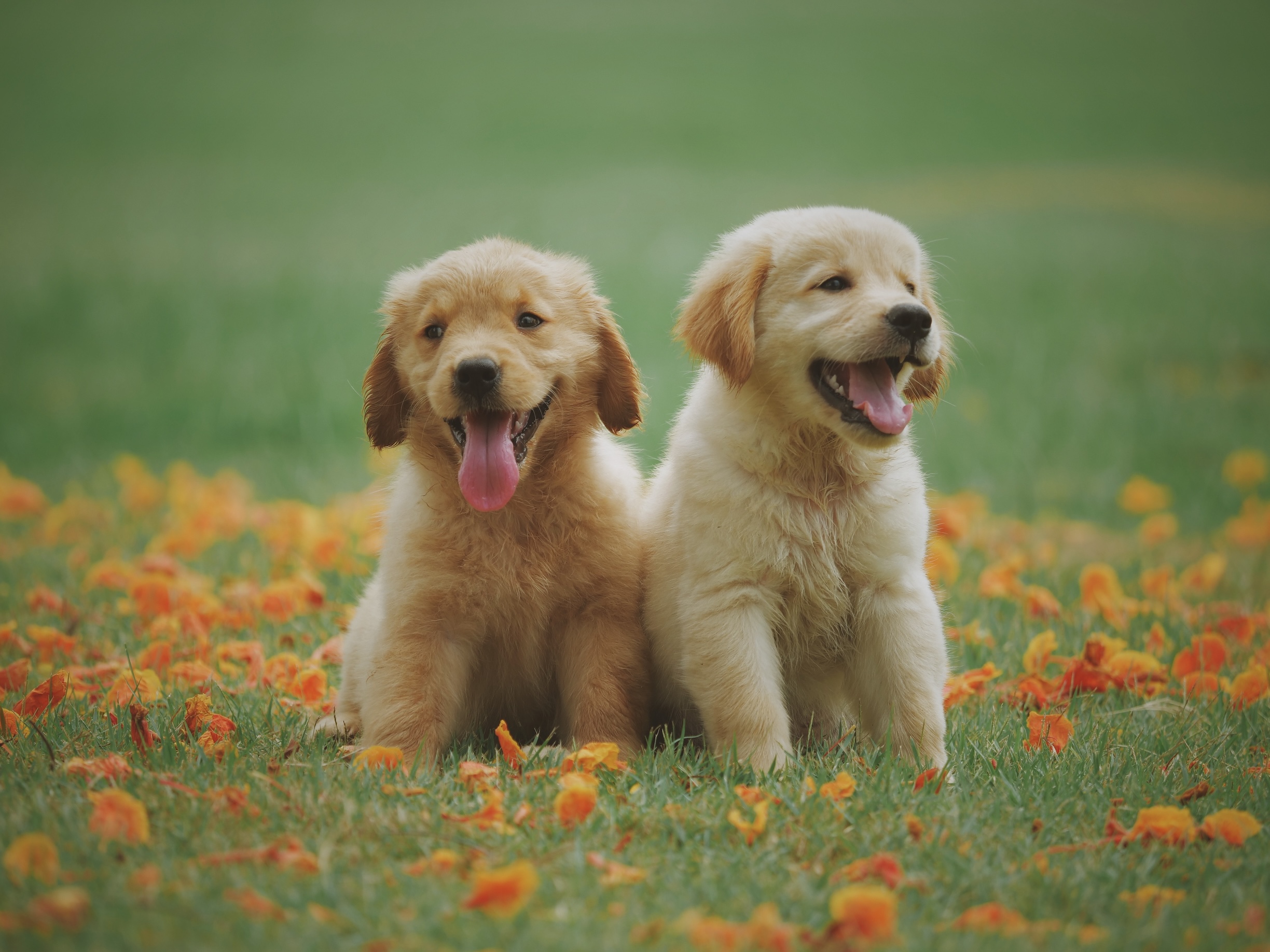
여러 히스토그램을 생성하는 것이 일반적입니다.
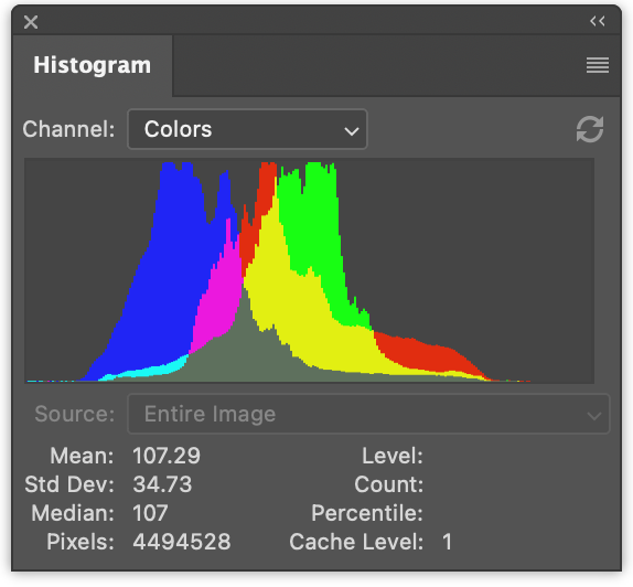
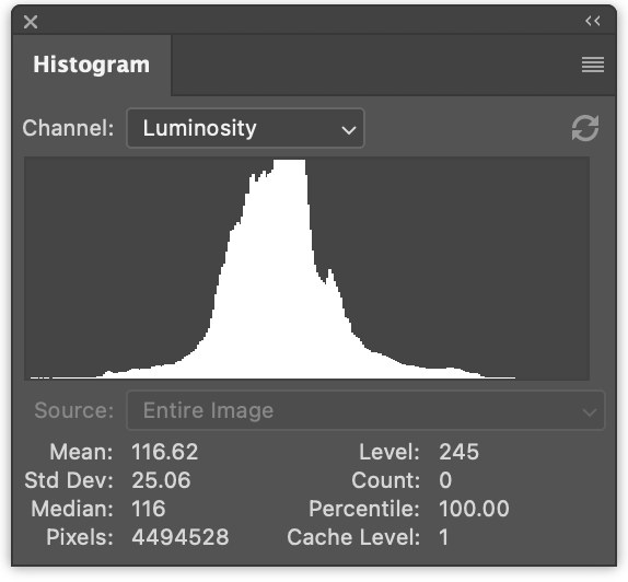
왼쪽에는 빨강, 초록, 파랑 값에 대한 3개의 히스토그램이 있습니다. 겹쳐서 그려집니다. 오른쪽에는 이전 문서에서 생성한 것과 같은 휘도 히스토그램이 있습니다.
한 번에 4개를 모두 생성하는 것은 아주 작은 변경입니다.
JavaScript에서 한 번에 4개의 히스토그램을 생성하기 위한 변경 사항은 다음과 같습니다.
function computeHistogram(numBins, imgData) {
  const {width, height, data} = imgData;
-  const bins = new Array(numBins).fill(0);
+  const bins = new Array(numBins * 4).fill(0);
  for (let y = 0; y < height; ++y) {
    for (let x = 0; x < width; ++x) {
      const offset = (y * width + x) * 4;

-      const r = data[offset + 0] / 255;
-      const g = data[offset + 1] / 255;
-      const b = data[offset + 2] / 255;
-      const v = srgbLuminance(r, g, b);
-
-      const bin = Math.min(numBins - 1, v * numBins) | 0;
-      ++bins[bin];

+       for (const ch = 0; ch < 4; ++ch) {
+          const v = ch < 3
+             ? data[offset + ch] / 255
+             : srgbLuminance(data[offset + 0] / 255,
+                             data[offset + 1] / 255,
+                             data[offset + 2] / 255);
+          const bin = Math.min(numBins - 1, v * numBins) | 0;
+          ++bins[bin * 4 + ch];
+       }
    }
  }
  return bins;
}
이렇게 하면 히스토그램이 인터리브되어(서로서로 사이에 낀 형태로) 생성됩니다. r, g, b, l, r, g, b, l, r, g, b, l …
다음과 같이 렌더링하도록 코드를 업데이트할 수 있습니다.
function drawHistogram(histogram, numEntries, channels, height = 100) {
-  const numBins = histogram.length;
-  const max = Math.max(...histogram);
-  const scale = Math.max(1 / max);//, 0.2 * numBins / numEntries);
+  // 각 채널의 최고 값 찾기
+  const numBins = histogram.length / 4;
+  const max = [0, 0, 0, 0];
+  histogram.forEach((v, ndx) => {
+    const ch = ndx % 4;
+    max[ch] = Math.max(max[ch], v);
+  });
+  const scale = max.map(max => Math.max(1 / max, 0.2 * numBins / numEntries));

  const canvas = document.createElement('canvas');
  canvas.width = numBins;
  canvas.height = height;
  document.body.appendChild(canvas);
  const ctx = canvas.getContext('2d');

+  const colors = [
+    'rgb(255, 0, 0)',
+    'rgb(0, 255, 0)',
+    'rgb(0, 0, 255)',
+    'rgb(255, 255, 255)',
+  ];

-  ctx.fillStyle = '#fff';
+  ctx.globalCompositeOperation = 'screen';

  for (let x = 0; x < numBins; ++x) {
-    const v = histogram[x] * scale * height;
-    ctx.fillRect(x, height - v, 1, v);
+    const offset = x * 4;
+    for (const ch of channels) {
+      const v = histogram[offset + ch] * scale[ch] * height;
+      ctx.fillStyle = colors[ch];
+      ctx.fillRect(x, height - v, 1, v);
+    }
  }
}
그런 다음 해당 함수를 두 번 호출합니다. 한 번은 색상 히스토그램을 렌더링하고 한 번은 휘도 히스토그램을 렌더링합니다.
  const histogram = computeHistogram(numBins, imgData);

  showImageBitmap(imgBitmap);

+  // 빨강, 초록, 파랑 채널 그리기
  const numEntries = imgData.width * imgData.height;
-  drawHistogram(histogram, numEntries);
+  drawHistogram(histogram, numEntries, [0, 1, 2]);
+
+  // 휘도 채널 그리기
+  drawHistogram(histogram, numEntries, [3]);
이제 이러한 결과를 얻습니다.
WGSL 예제에 동일한 작업을 수행하는 것은 훨씬 더 간단합니다.
예를 들어 너무 느렸던 첫 번째 예제는 다음과 같이 변경됩니다.
-@group(0) @binding(0) var<storage, read_write> bins: array<u32>;
+@group(0) @binding(0) var<storage, read_write> bins: array<vec4u>;
@group(0) @binding(1) var ourTexture: texture_2d<f32>;

// from: https://www.w3.org/WAI/GL/wiki/Relative_luminance
const kSRGBLuminanceFactors = vec3f(0.2126, 0.7152, 0.0722);
fn srgbLuminance(color: vec3f) -> f32 {
  return saturate(dot(color, kSRGBLuminanceFactors));
}

@compute @workgroup_size(1, 1, 1) fn cs() {
  let size = textureDimensions(ourTexture, 0);
  let numBins = f32(arrayLength(&bins));
  let lastBinIndex = u32(numBins - 1);
  for (var y = 0u; y < size.y; y++) {
    for (var x = 0u; x < size.x; x++) {
      let position = vec2u(x, y);
-      let color = textureLoad(ourTexture, position, 0);
-      let v = srgbLuminance(color.rgb);
-      let bin = min(u32(v * numBins), lastBinIndex);
-      bins[bin] += 1;
+      var channels = textureLoad(ourTexture, position, 0);
+      channels.w = srgbLuminance(channels.rgb);
+      for (var ch = 0; ch < 4; ch++) {
+        let v = channels[ch];
+        let bin = min(u32(v * numBins), lastBinIndex);
+        bins[bin][ch] += 1;
+      }
    }
  }
}
4개의 채널 모두를 위한 공간을 만들기 위해 bins를
array<u32>에서 array<vec4u>로 변경해야 했습니다.
그런 다음 텍스처에서 색상을 가져와 휘도를 계산하고
channels의 w 요소에 넣었습니다.
  var channels = textureLoad(ourTexture, position, 0);
  channels.w = srgbLuminance(channels.rgb);
이렇게 하면 4개의 채널을 반복하고 올바른 빈을 증가시킬 수 있습니다.
필요한 다른 변경 사항은 버퍼에 4배의 메모리를 할당하는 것입니다.
  const histogramBuffer = device.createBuffer({
-    size: numBins * 4, // 256 entries * 4 bytes per (u32)
+    size: 256 * 4 * 4, // 256 entries * 4 (rgba) * 4 bytes per (u32)
    usage: GPUBufferUsage.STORAGE | GPUBufferUsage.COPY_SRC,
  });
그리고 여기 4개의 히스토그램을 생성하는 느린 WebGPU 버전이 있습니다.
가장 빠른 버전에 유사한 변경을 수행합니다.
const chunkWidth = 256;
const chunkHeight = 1;
const chunkSize = chunkWidth * chunkHeight;
-var<workgroup> bins: array<atomic<u32>, chunkSize>;
-@group(0) @binding(0) var<storage, read_write> chunks: array<array<u32, chunkSize>>;
+var<workgroup> bins: array<array<atomic<u32>, 4>, chunkSize>;
+@group(0) @binding(0) var<storage, read_write> chunks: array<array<vec4u, chunkSize>>;
@group(0) @binding(1) var ourTexture: texture_2d<f32>;

const kSRGBLuminanceFactors = vec3f(0.2126, 0.7152, 0.0722);
fn srgbLuminance(color: vec3f) -> f32 {
  return saturate(dot(color, kSRGBLuminanceFactors));
}

@compute @workgroup_size(chunkWidth, chunkHeight, 1)
fn cs(
  @builtin(workgroup_id) workgroup_id: vec3u,
  @builtin(local_invocation_id) local_invocation_id: vec3u,
) {
  let size = textureDimensions(ourTexture, 0);
  let position = workgroup_id.xy * vec2u(chunkWidth, chunkHeight) +
                 local_invocation_id.xy;
  if (all(position < size)) {
    let numBins = f32(chunkSize);
    let lastBinIndex = u32(numBins - 1);
-    let color = textureLoad(ourTexture, position, 0);
-    let v = srgbLuminance(color.rgb);
-    let bin = min(u32(v * numBins), lastBinIndex);
-    atomicAdd(&bins[bin], 1u);
+    var channels = textureLoad(ourTexture, position, 0);
+    channels.w = srgbLuminance(channels.rgb);
+    for (var ch = 0; ch < 4; ch++) {
+      let v = channels[ch];
+      let bin = min(u32(v * numBins), lastBinIndex);
+      atomicAdd(&bins[bin][ch], 1u);
+    }
  }

  workgroupBarrier();

  let chunksAcross = (size.x + chunkWidth - 1) / chunkWidth;
  let chunk = workgroup_id.y * chunksAcross + workgroup_id.x;
  let bin = local_invocation_id.y * chunkWidth + local_invocation_id.x;

-  chunks[chunk][bin] = atomicLoad(&bins[bin]);
+  chunks[chunk][bin] = vec4u(
+    atomicLoad(&bins[bin][0]),
+    atomicLoad(&bins[bin][1]),
+    atomicLoad(&bins[bin][2]),
+    atomicLoad(&bins[bin][3]),
+  );
}
그리고 리듀스 셰이더의 경우
const chunkWidth = 256;
const chunkHeight = 1;
const chunkSize = chunkWidth * chunkHeight;

struct Uniforms {
  stride: u32,
};

-@group(0) @binding(0) var<storage, read_write> chunks: array<array<u32, chunkSize>>;
+@group(0) @binding(0) var<storage, read_write> chunks: array<array<vec4u, chunkSize>>;
@group(0) @binding(1) var<uniform> uni: Uniforms;

@compute @workgroup_size(chunkSize, 1, 1) fn cs(
  @builtin(local_invocation_id) local_invocation_id: vec3u,
  @builtin(workgroup_id) workgroup_id: vec3u,
) {
  let chunk0 = workgroup_id.x * uni.stride * 2;
  let chunk1 = chunk0 + uni.stride;

  let sum = chunks[chunk0][local_invocation_id.x] +
            chunks[chunk1][local_invocation_id.x];
  chunks[chunk0][local_invocation_id.x] = sum;
}
이전 예제와 마찬가지로 버퍼 크기를 늘려야 합니다.
  const chunksBuffer = device.createBuffer({
-    size: numChunks * chunkSize * 4,  // 4 bytes per (u32)
+    size: numChunks * chunkSize * 4 * 4,  // 16 bytes per (vec4u)
    usage: GPUBufferUsage.STORAGE | GPUBufferUsage.COPY_SRC,
  });

  const resultBuffer = device.createBuffer({
-    size: chunkSize * 4,
+    size: chunkSize * 4 * 4,
    usage: GPUBufferUsage.COPY_DST | GPUBufferUsage.MAP_READ,
  });
그게 전부입니다.
이전 문서에서 시도한 다른 2단계가 있었습니다. 하나는 픽셀당 단일 워크그룹을 사용했습니다. 다른 하나는 빈을 줄이는 대신 빈당 호출로 청크를 합산했습니다.
다음은 이러한 4채널 버전을 테스트하여 얻은 타이밍 정보입니다.
이전 문서의 1채널 버전과 비교할 수 있습니다.
GPU에서 히스토그램 그리기
GPU에서 히스토그램을 그려봅시다. JavaScript에서는 canvas 2d API를 사용하여 각 빈에 대해 1 x height 직사각형을 그렸는데 매우 쉬웠습니다. WebGPU를 사용하여 동일한 작업을 수행할 수 있습니다. 히스토그램을 그리는 더 나은 접근 방식도 충분히 있을거라고 생각합니다.
어쨋든 직사각형을 하나 그려봅시다. 직사각형 그리기는 여러 곳에서 다루었습니다. 예를 들어 텍스처에 관한 문서의 대부분의 예제는 직사각형을 사용합니다.
히스토그램의 경우 프래그먼트 셰이더에서 텍스처 좌표를 전달하고 수평 부분을 0 -> 1에서 0 -> numBins - 1로 변환할 수 있습니다. 그런 다음 해당 빈의 값을 조회하고 0에서 1 범위의 높이를 계산할 수 있습니다. 그런 다음 이를 수직 텍스처 좌표와 비교할 수 있습니다. 텍스처 좌표가 높이보다 높으면 0을 그릴 수 있고, 높이보다 낮으면 일부 색상을 그릴 수 있습니다.
이것은 1채널에 대해 작동하지만 여러 채널을 그리고 싶습니다. 이번에는 위에서 설명한 데로 계산한 높이보다 높이 값이 높은 채널에 대해 하나씩 비트를 설정한 다음 이 4비트를 사용하여 16가지 색상 중 하나를 조회합니다. 이렇게 하면 각 채널과 그 조합을 나타내는 색상을 선택할 수도 있습니다.
이를 수행하는 프래그먼트 셰이더는 다음과 같습니다.
struct Uniforms {
  matrix: mat4x4f,  // <- 버텍스 셰이더에서 사용
  colors: array<vec4f, 16>,
  channelMult: vec4u,
};

@group(0) @binding(0) var<storage, read> bins: array<vec4u>;
@group(0) @binding(1) var<uniform> uni: Uniforms;
@group(0) @binding(2) var<storage, read_write> scale: vec4f;

@fragment fn fs(fsInput: OurVertexShaderOutput) -> @location(0) vec4f {
  let numBins = arrayLength(&bins);
  let lastBinIndex = u32(numBins - 1);
  let bin = clamp(
      u32(fsInput.texcoord.x * f32(numBins)),
      0,
      lastBinIndex);
  let heights = vec4f(bins[bin]) * scale;
  let bits = heights > vec4f(fsInput.texcoord.y);
  let ndx = dot(select(vec4u(0), uni.channelMult, bits), vec4u(1));
  return uni.colors[ndx];
}
첫 번째 부분은 수평 텍스처 좌표를 기반으로 어떤 빈인지 계산합니다.
  let numBins = arrayLength(&bins);
  let lastBinIndex = u32(numBins - 1);
  let bin = clamp(
      u32(fsInput.texcoord.x * f32(numBins)),
      0,
      lastBinIndex);
다음 부분은 모든 4개 채널의 높이를 가져옵니다.
JavaScript에서 했던 것처럼 scale을 곱합니다. 나중에 이를 제공해야 합니다.
let heights = vec4f(bins[bin]) * scale;
다음으로 vec4<bool>에 4개의 부울을 설정합니다.
각 채널에 대해 하나씩. 빈의 높이가
텍스처 좌표보다 높으면 true가 됩니다.
let bits = heights > vec4f(fsInput.texcoord.y);
다음 부분은 이 4개의 부울을 기반으로 uni.channelMult에서 값을 선택한 다음
4개의 값을 더합니다.
uni.channelMult를 전달할 수 있다는 것은
JavaScript에서 했던 것과 유사하여 어떤 채널을 그릴지 선택할 수 있습니다. 예를 들어
channelMult를 1, 2, 4, 0으로 설정하면 빨강, 초록,
파랑 히스토그램을 얻습니다.
let ndx = dot(select(vec4u(0), uni.channelMult, bits), vec4u(1));
마지막 부분은 16가지 색상 중 하나를 조회합니다.
return uni.colors[ndx];
scale을 계산하는 셰이더도 필요합니다. JavaScript에서는
다음과 같이 했습니다.
  const numBins = histogram.length / 4;
  const max = [0, 0, 0, 0];
  histogram.forEach((v, ndx) => {
    const ch = ndx % 4;
    max[ch] = Math.max(max[ch], v);
  });
  const scale = max.map(max => Math.max(1 / max, 0.2 * numBins / numEntries));
컴퓨트 셰이더에서 동일한 작업을 수행하려면 다음과 같이 할 수 있습니다.
@group(0) @binding(0) var<storage, read> bins: array<vec4u>;
@group(0) @binding(1) var<storage, read_write> scale: vec4f;
@group(0) @binding(2) var ourTexture: texture_2d<f32>;

@compute @workgroup_size(1, 1, 1) fn cs() {
  let size = textureDimensions(ourTexture, 0);
  let numEntries = f32(size.x * size.y);
  var m = vec4u(0);
  let numBins = arrayLength(&bins);
  for (var i = 0u ; i < numBins; i++) {
    m = max(m, bins[i]);
  }
  scale = max(1.0 / vec4f(m), vec4f(0.2 * f32(numBins) / numEntries));
}
ourTexture를 전달하는 유일한 이유는 크기를 가져와서
numEntries를 계산할 수 있도록 하기 위함입니다. JavaScript에서는 numEntries를 전달했습니다.
유니폼을 사용하여 numEntries를 전달할 수도 있지만 그러면
유니폼 버퍼를 만들고, numEntries 값으로 업데이트하고, 바인드
등을 해야 합니다… 텍스처 자체를 참조하는 것이 더 쉬워 보였습니다.
고려해야 할 또 다른 사항은 이것이
단일 코어만 사용하는 또 다른 장소라는 것입니다. 여기서도 리듀스할 수 있지만 numBins 단계만
있으며 이는 256에 불과합니다. 여러 리듀스 단계를 디스패치하는 오버헤드가
병렬화를 아마도 능가할 것입니다. 타이밍을 측정해보니
적어도 한 컴퓨터에서는 약 0.1ms라고 했습니다.
그래서 남은 것은 부품을 조립하는 것입니다.
GPU로 캔버스에 그릴 것이므로 선호하는 캔버스 형식을 가져와야 합니다.
const presentationFormat = navigator.gpu.getPreferredCanvasFormat();
위의 2개의 셰이더로 셰이더 모듈을 만들고 각각에 대한 파이프라인을 만들어야 합니다.
  const scaleModule = device.createShaderModule({
    label: 'histogram scale shader',
    code: /* wgsl */ `
      @group(0) @binding(0) var<storage, read> bins: array<vec4u>;
      @group(0) @binding(1) var<storage, read_write> scale: vec4f;
      @group(0) @binding(2) var ourTexture: texture_2d<f32>;

      @compute @workgroup_size(1, 1, 1) fn cs() {
        let size = textureDimensions(ourTexture, 0);
        let numEntries = f32(size.x * size.y);
        var m = vec4u(0);
        let numBins = arrayLength(&bins);
        for (var i = 0u ; i < numBins; i++) {
          m = max(m, bins[i]);
        }
        scale = max(1.0 / vec4f(m), vec4f(0.2 * f32(numBins) / numEntries));
      }
    `,
  });

  const drawHistogramModule = device.createShaderModule({
    label: 'draw histogram shader',
    code: /* wgsl */ `
      struct OurVertexShaderOutput {
        @builtin(position) position: vec4f,
        @location(0) texcoord: vec2f,
      };

      struct Uniforms {
        matrix: mat4x4f,
        colors: array<vec4f, 16>,
        channelMult: vec4u,
      };

      @group(0) @binding(0) var<storage, read> bins: array<vec4u>;
      @group(0) @binding(1) var<uniform> uni: Uniforms;
      @group(0) @binding(2) var<storage, read_write> scale: vec4f;

      @vertex fn vs(
        @builtin(vertex_index) vertexIndex : u32
      ) -> OurVertexShaderOutput {
        let pos = array(
          // 1st triangle
          vec2f( 0.0,  0.0),  // center
          vec2f( 1.0,  0.0),  // right, center
          vec2f( 0.0,  1.0),  // center, top

          // 2nd triangle
          vec2f( 0.0,  1.0),  // center, top
          vec2f( 1.0,  0.0),  // right, center
          vec2f( 1.0,  1.0),  // right, top
        );

        var vsOutput: OurVertexShaderOutput;
        let xy = pos[vertexIndex];
        vsOutput.position = uni.matrix * vec4f(xy, 0.0, 1.0);
        vsOutput.texcoord = xy;
        return vsOutput;
      }

      @fragment fn fs(fsInput: OurVertexShaderOutput) -> @location(0) vec4f {
        let numBins = arrayLength(&bins);
        let lastBinIndex = u32(numBins - 1);
        let bin = clamp(
            u32(fsInput.texcoord.x * f32(numBins)),
            0,
            lastBinIndex);
        let heights = vec4f(bins[bin]) * scale;
        let bits = heights > vec4f(fsInput.texcoord.y);
        let ndx = dot(select(vec4u(0), uni.channelMult, bits), vec4u(1));
        return uni.colors[ndx];
      }
    `,
  });

  const scalePipeline = device.createComputePipeline({
    label: 'scale',
    layout: 'auto',
    compute: {
      module: scaleModule,
    },
  });

  const drawHistogramPipeline = device.createRenderPipeline({
    label: 'draw histogram',
    layout: 'auto',
    vertex: {
      module: drawHistogramModule,
    },
    fragment: {
      module: drawHistogramModule,
      targets: [{ format: presentationFormat }],
    },
  });
값을 다시 읽지 않을 것이므로 결과 버퍼가 더 이상 필요하지 않지만 계산할 스케일을 저장하기 위한 스케일 버퍼가 필요합니다.
-  const resultBuffer = device.createBuffer({
-    size: chunkSize * 4 * 4,
-    usage: GPUBufferUsage.COPY_DST | GPUBufferUsage.MAP_READ,
-  });
+  const scaleBuffer = device.createBuffer({
+    size: 4 * 4,
+    usage: GPUBufferUsage.STORAGE,
+  });
청크, 스케일 버퍼, 텍스처가 있는 스케일 파이프라인에 대한 바인드 그룹이 필요합니다.
  const scaleBindGroup = device.createBindGroup({
    layout: scalePipeline.getBindGroupLayout(0),
    entries: [
      {
        binding: 0,
        resource: {
          buffer: chunksBuffer,
          size: chunkSize * 4 * 4,
        },
      },
      { binding: 1, resource: scaleBuffer },
      { binding: 2, resource: texture },
    ],
  });
위에서 chunksBuffer에 대한 바인딩 크기를
첫 번째 청크의 크기로만 설정했습니다. 이렇게 하면
셰이더에서 이 코드가
      @group(0) @binding(0) var<storage, read> bins: array<vec4u>;

      ...

        let numBins = arrayLength(&bins);
올바른 값을 얻습니다. 크기를 지정하지 않으면
전체 chunksBuffer 크기를 사용할 수 있고
numBins는 첫 번째 청크가 아닌 모든 청크에서 계산됩니다.
이제 청크를 하나의 청크로 줄인 후 스케일 컴퓨트 셰이더를 실행하여
스케일을 계산할 수 있으며, 더 이상 결과 버퍼가 없으므로
첫 번째 청크를 복사할 필요가 없으며, 결과 버퍼를 매핑할 필요도 없으며,
스케일을 계산하는 데 사용했던 numEntries를 전달할 필요도 없습니다.
또한 결과 버퍼에서 가져온 데이터인 histogram을 전달하지 않을 것입니다.
데이터는 이미 chunksBuffer에 있습니다.
+  // 채널에 대한 스케일 계산
+  pass.setPipeline(scalePipeline);
+  pass.setBindGroup(0, scaleBindGroup);
+  pass.dispatchWorkgroups(1);
  pass.end();

-  encoder.copyBufferToBuffer(chunksBuffer, 0, resultBuffer, 0, resultBuffer.size);
  const commandBuffer = encoder.finish();
  device.queue.submit([commandBuffer]);

-  await resultBuffer.mapAsync(GPUMapMode.READ);
-  const histogram = new Uint32Array(resultBuffer.getMappedRange());

  showImageBitmap(imgBitmap);

  // 빨강, 초록, 파랑 채널 그리기
-  const numEntries = texture.width * texture.height;
-  drawHistogram(histogram, numEntries, [0, 1, 2]);
+  drawHistogram([0, 1, 2]);

  // 휘도 채널 그리기
-  drawHistogram(histogram, numEntries, [3]);
+  drawHistogram([3]);

-  resultBuffer.unmap();
이제 GPU로 렌더링하도록 drawHistogram 함수를 업데이트해야 합니다.
먼저 유니폼을 전달하기 위한 유니폼 버퍼를 만들어야 합니다. 참고로 히스토그램을 그릴 셰이더의 유니폼은 다음과 같습니다.
struct Uniforms {
  matrix: mat4x4f,
  colors: array<vec4f, 16>,
  channelMult: vec4u,
};
따라서 다음은 버퍼를 만들고 channelMult와 colors를 채우는 코드입니다.
  function drawHistogram(channels, height = 100) {
    const numBins = chunkSize;

    //  matrix: mat4x4f;
    //  colors: array<vec4f, 16>;
    //  channelMult; vec4u,
    const uniformValuesAsF32 = new Float32Array(16 + 64 + 4 + 4);
    const uniformValuesAsU32 = new Uint32Array(uniformValuesAsF32.buffer);
    const uniformBuffer = device.createBuffer({
      label: 'draw histogram uniform buffer',
      size: uniformValuesAsF32.byteLength,
      usage: GPUBufferUsage.UNIFORM | GPUBufferUsage.COPY_DST,
    });
    const subpart = (view, offset, length) => view.subarray(offset, offset + length);
    const matrix = subpart(uniformValuesAsF32, 0, 16);
    const colors = subpart(uniformValuesAsF32, 16, 64);
    const channelMult = subpart(uniformValuesAsU32, 16 + 64, 4);
    channelMult.set(range(4, i => channels.indexOf(i) >= 0 ? 2 ** i : 0));
    colors.set([
      [0, 0, 0, 1],
      [1, 0, 0, 1],
      [0, 1, 0, 1],
      [1, 1, 0, 1],
      [0, 0, 1, 1],
      [1, 0, 1, 1],
      [0, 1, 1, 1],
      [0.5, 0.5, 0.5, 1],
      [1, 1, 1, 1],
      [1, 1, 1, 1],
      [1, 1, 1, 1],
      [1, 1, 1, 1],
      [1, 1, 1, 1],
      [1, 1, 1, 1],
      [1, 1, 1, 1],
      [1, 1, 1, 1],
    ].flat());
    const range = (i, fn) => new Array(i).fill(0).map((_, i) => fn(i));
    channelMult.set(range(4, i => channels.indexOf(i) >= 0 ? 2 ** i : 0));
행렬 수학에 관한 일련의 문서에서 다룬 것처럼 행렬 수학을 사용하여 행렬을 계산해야 합니다.
특히 우리의 셰이더에는 X와 Y 모두에서 0에서 1까지 가는 하드코딩된 단위 쿼드(quad)가 있습니다. X와 Y 모두에서 2로 스케일하고 1을 빼면 클립 공간을 커버하는 양방향으로 -1에서 +1까지 가는 쿼드를 얻습니다. 단일 단위 쿼드를 사용하는 이 방법은 일반적입니다. 그런 다음 약간의 행렬 수학을 사용하여 특수 버텍스 데이터를 만들 필요 없이 모든 위치와 방향의 직사각형을 그릴 수 있습니다.
    mat4.identity(matrix);
    mat4.translate(matrix, [-1, -1, 0], matrix);
    mat4.scale(matrix, [2, 2, 1], matrix);
    device.queue.writeBuffer(uniformBuffer, 0, uniformValuesAsF32);
이 모든 것에 대한 bindGroup이 필요합니다.
    const bindGroup = device.createBindGroup({
      layout: drawHistogramPipeline.getBindGroupLayout(0),
      entries: [
        { binding: 0, resource: { buffer: chunksBuffer, size: chunkSize * 4 * 4 }},
        { binding: 1, resource: uniformBuffer  },
        { binding: 2, resource: scaleBuffer },
      ],
    });
WebGPU용으로 구성된 캔버스가 필요합니다.
    const canvas = document.createElement('canvas');
    const context = canvas.getContext('webgpu');
    context.configure({
      device,
      format: presentationFormat,
    });
    canvas.width = numBins;
    canvas.height = height;
    document.body.appendChild(canvas);
마지막으로 렌더링할 수 있습니다.
    // 캔버스 컨텍스트에서 현재 텍스처를 가져와서
    // 렌더링할 텍스처로 설정합니다.
    const renderPassDescriptor = {
      label: 'our basic canvas renderPass',
      colorAttachments: [
        {
          view: context.getCurrentTexture().createView(),
          clearValue: [0.3, 0.3, 0.3, 1],
          loadOp: 'clear',
          storeOp: 'store',
        },
      ],
    };

    const encoder = device.createCommandEncoder({ label: 'render histogram' });
    const pass = encoder.beginRenderPass(renderPassDescriptor);
    pass.setPipeline(drawHistogramPipeline);
    pass.setBindGroup(0, bindGroup);
    pass.draw(6);  // 버텍스 셰이더를 6번 호출
    pass.end();

    const commandBuffer = encoder.finish();
    device.queue.submit([commandBuffer]);
  }
그리고 이 모든 것으로 GPU에서 렌더링하고 있습니다.
마지막으로 한 가지 더 해봅시다. 비디오의 히스토그램을 가져와봅시다. 효과적으로 외부 비디오 사용에 관한 문서의 예제와 이전 예제를 병합할 것입니다.
비디오 예제와 일치하도록 HTML과 CSS를 업데이트해야 합니다.
    <style>
      @import url(resources/webgpu-lesson.css);
+html, body {
+  margin: 0;       /* 기본 여백 제거          */
+  height: 100%;    /* html,body가 페이지를 채우도록   */
+}
canvas {
+  display: block;  /* 캔버스가 블록처럼 동작하도록   */
+  width: 100%;     /* 캔버스가 컨테이너를 채우도록 */
+  height: 100%;
-  max-width: 256px;
-  border: 1px solid #888;
}
+#start {
+  position: fixed;
+  left: 0;
+  top: 0;
+  width: 100%;
+  height: 100%;
+  display: flex;
+  justify-content: center;
+  align-items: center;
+}
+#start>div {
+  font-size: 200px;
+  cursor: pointer;
+}
    </style>
  </head>
  <body>
+    <canvas></canvas>
+    <div id="start">
+      <div>▶️</div>
+    </div>
  </body>
맨 처음에 하나의 캔버스를 설정하겠습니다.
  // 캔버스에서 WebGPU 컨텍스트를 가져와 구성합니다
  const canvas = document.querySelector('canvas');
  const context = canvas.getContext('webgpu');
  const presentationFormat = navigator.gpu.getPreferredCanvasFormat();
  context.configure({
    device,
    format: presentationFormat,
  });
외부 텍스처를 사용하고 있기 때문에 해당 종류의 텍스처에 대한 셰이더를 변경해야 합니다. 예를 들어 히스토그램 청크 만들기 셰이더에는 다음과 같은 변경이 필요합니다.
const chunkSize = chunkWidth * chunkHeight;
var<workgroup> bins: array<array<atomic<u32>, 4>, chunkSize>;
@group(0) @binding(0) var<storage, read_write> chunks: array<array<vec4u, chunkSize>>;
-@group(0) @binding(1) var ourTexture: texture_2d<f32>;
+@group(0) @binding(1) var ourTexture: texture_external;

const kSRGBLuminanceFactors = vec3f(0.2126, 0.7152, 0.0722);
fn srgbLuminance(color: vec3f) -> f32 {
  return saturate(dot(color, kSRGBLuminanceFactors));
}

@compute @workgroup_size(chunkWidth, chunkHeight, 1)
fn cs(
  @builtin(workgroup_id) workgroup_id: vec3u,
  @builtin(local_invocation_id) local_invocation_id: vec3u,
) {
-  let size = textureDimensions(ourTexture, 0);
+  let size = textureDimensions(ourTexture);
  let position = workgroup_id.xy * vec2u(chunkWidth, chunkHeight) +
                 local_invocation_id.xy;
  if (all(position < size)) {
    let numBins = f32(chunkSize);
    let lastBinIndex = u32(numBins - 1);
-    var channels = textureLoad(ourTexture, position, 0);
+    var channels = textureLoad(ourTexture, position);
    channels.w = srgbLuminance(channels.rgb);
    for (var ch = 0; ch < 4; ch++) {
      let v = channels[ch];
      let bin = min(u32(v * numBins), lastBinIndex);
      atomicAdd(&bins[bin][ch], 1u);
    }
  }

...
스케일 계산 셰이더에도 유사한 변경 사항이 있습니다.
@group(0) @binding(0) var<storage, read> bins: array<vec4u>;
@group(0) @binding(1) var<storage, read_write> scale: vec4f;
-@group(0) @binding(2) var ourTexture: texture_2d<f32>;
+@group(0) @binding(2) var ourTexture: texture_external;

@compute @workgroup_size(1, 1, 1) fn cs() {
-  let size = textureDimensions(ourTexture, 0);
+  let size = textureDimensions(ourTexture);
  let numEntries = f32(size.x * size.y);

  ...
비디오를 그리는 셰이더 모듈은 비디오 문서에서 직접 복사되며 이를 사용하는 렌더 파이프라인 생성과 비디오용 샘플러 및 유니폼 버퍼 및 렌더 패스도 마찬가지입니다. 클릭을 기다리고 비디오 재생을 시작하는 동일한 코드가 있습니다.
비디오가 시작되면 히스토그램 계산을 설정할 수 있습니다. 유일한 변경 사항은 텍스처가 아닌 비디오에서 크기를 가져온다는 것입니다.
-  const imgBitmap = await loadImageBitmap('resources/images/pexels-francesco-ungaro-96938-mid.jpg');
-  const texture = createTextureFromSource(device, imgBitmap);

-  const chunksAcross = Math.ceil(texture.width / k.chunkWidth);
-  const chunksDown = Math.ceil(texture.height / k.chunkHeight);
+  const chunksAcross = Math.ceil(video.videoWidth / k.chunkWidth);
+  const chunksDown = Math.ceil(vide.videoHeight / k.chunkHeight);
히스토그램을 그리는 코드를 drawHistogram에 넣었지만
해당 코드는 자체 캔버스를 만들고 한 번만 사용되는 다른 것들을 만들었습니다.
drawHistogram을 제거하고 그리려는 2개의 히스토그램 각각에 대해
유니폼 버퍼와 바인드 그룹을 설정하는 코드를 만들겠습니다.
  const histogramDrawInfos = [
    [0, 1, 2],
    [3],
  ].map(channels => {
    //        matrix: mat4x4f;
    //        colors: array<vec4f, 16>;
    //        channelMult; vec4u,
    const uniformValuesAsF32 = new Float32Array(16 + 64 + 4 + 4);
    const uniformValuesAsU32 = new Uint32Array(uniformValuesAsF32.buffer);
    const uniformBuffer = device.createBuffer({
      label: 'draw histogram uniform buffer',
      size: uniformValuesAsF32.byteLength,
      usage: GPUBufferUsage.UNIFORM | GPUBufferUsage.COPY_DST,
    });
    thingsToDestroy.push(uniformBuffer);
    const subpart = (view, offset, length) => view.subarray(offset, offset + length);
    const matrix = subpart(uniformValuesAsF32, 0, 16);
    const colors = subpart(uniformValuesAsF32, 16, 64);
    const channelMult = subpart(uniformValuesAsU32, 16 + 64, 4);
    colors.set([
      [0, 0, 0, 1],
      [1, 0, 0, 1],
      [0, 1, 0, 1],
      [1, 1, 0, 1],
      [0, 0, 1, 1],
      [1, 0, 1, 1],
      [0, 1, 1, 1],
      [0.5, 0.5, 0.5, 1],
      [1, 1, 1, 1],
      [1, 1, 1, 1],
      [1, 1, 1, 1],
      [1, 1, 1, 1],
      [1, 1, 1, 1],
      [1, 1, 1, 1],
      [1, 1, 1, 1],
      [1, 1, 1, 1],
    ].flat());

    const drawHistogramBindGroup = device.createBindGroup({
      layout: drawHistogramPipeline.getBindGroupLayout(0),
      entries: [
        { binding: 0, resource: { buffer: chunksBuffer, size: chunkSize * 4 * 4 }},
        { binding: 1, resource: uniformBuffer  },
        { binding: 2, resource: scaleBuffer },
      ],
    });

    return {
      drawHistogramBindGroup,
      matrix,
      uniformBuffer,
      uniformValuesAsF32,
    };
  });
렌더 시간에 먼저 비디오 텍스처를 가져옵니다. 기억하세요, 이것은 이 하나의 JavaScript 이벤트에 대해서만 유효하므로 텍스처를 참조하는 바인드 그룹을 매 프레임마다 만들어야 합니다.
  function render() {
    const texture = device.importExternalTexture({source: video});

    // 이 비디오 텍스처에서 히스토그램을 만들기 위한 바인드 그룹 만들기
    const histogramBindGroup = device.createBindGroup({
      layout: histogramChunkPipeline.getBindGroupLayout(0),
      entries: [
        { binding: 0, resource: chunksBuffer },
        { binding: 1, resource: texture },
      ],
    });

    const scaleBindGroup = device.createBindGroup({
      layout: scalePipeline.getBindGroupLayout(0),
      entries: [
        { binding: 0, resource: { buffer: chunksBuffer, size: chunkSize * 4 * 4 }},
        { binding: 1, resource: scaleBuffer },
        { binding: 2, resource: texture },
      ],
    });

    ... 여기에 히스토그램 계산 코드 삽입 ...
렌더링의 경우 비디오 렌더링은 외부 비디오 렌더링에 관한 문서와 유사합니다. 한 가지 차이점은 행렬을 계산하는 코드입니다. 히스토그램에 대해 위에서 언급한 것처럼 2로 스케일하고 1을 빼는 것을 하고 있지만 y에 -2를 곱하고 1을 더하여 Y를 뒤집습니다. 또한 스케일하여 비디오가 항상 캔버스를 채우지만 올바른 종횡비를 유지하도록 하는 커버 효과를 얻습니다.
    // 캔버스에 그리기
    {
      const canvasTexture = context.getCurrentTexture().createView();
      renderPassDescriptor.colorAttachments[0].view = canvasTexture;
      const pass = encoder.beginRenderPass(renderPassDescriptor);

      // 비디오 그리기
      const bindGroup = device.createBindGroup({
        layout: videoPipeline.getBindGroupLayout(0),
        entries: [
          { binding: 0, resource: videoSampler },
          { binding: 1, resource: texture },
          { binding: 2, resource: videoUniformBuffer },
        ],
      });

      // 캔버스 'cover'
      const canvasAspect = canvas.clientWidth / canvas.clientHeight;
      const videoAspect = video.videoWidth / video.videoHeight;
      const scale = canvasAspect > videoAspect
         ? [1, canvasAspect / videoAspect, 1]
         : [videoAspect / canvasAspect, 1, 1];

      const matrix = mat4.identity(videoMatrix);
      mat4.scale(matrix, scale, matrix);
      mat4.translate(matrix, [-1, 1, 0], matrix);
      mat4.scale(matrix, [2, -2, 1], matrix);

      device.queue.writeBuffer(videoUniformBuffer, 0, videoUniformValues);

      pass.setPipeline(videoPipeline);
      pass.setBindGroup(0, bindGroup);
      pass.draw(6);  // 버텍스 셰이더를 6번 호출
히스토그램을 그리는 것은 drawHistogram에서 코드를 옮기는 것입니다.
      // 히스토그램 그리기
      histogramDrawInfos.forEach(({
        matrix,
        uniformBuffer,
        uniformValuesAsF32,
        drawHistogramBindGroup,
      }, i) => {
        mat4.identity(matrix);
        mat4.translate(matrix, [-0.95 + i, -1, 0], matrix);
        mat4.scale(matrix, [0.9, 0.5, 1], matrix);

        device.queue.writeBuffer(uniformBuffer, 0, uniformValuesAsF32);

        pass.setPipeline(drawHistogramPipeline);
        pass.setBindGroup(0, drawHistogramBindGroup);
        pass.draw(6);  // 버텍스 셰이더를 6번 호출
      });

      pass.end();
    }

    const commandBuffer = encoder.finish();
    device.queue.submit([commandBuffer]);

    requestAnimationFrame(render);
  }
  requestAnimationFrame(render);
위의 행렬 수학은 캔버스의 절반 너비의 90%이고 해당 절반의 중앙에 위치하며 캔버스 높이의 ¼인 쿼드를 왼쪽 또는 오른쪽에 그립니다.
좋습니다. 그렇다면 왜 히스토그램을 계산할까요? 히스토그램으로 할 수 있는 몇 가지가 있습니다.
- 사용자에게 표시하여 이미지 조정에 대한 정보에 입각한 결정을 내릴 수 있도록 합니다
- 이미지에 히스토그램 평활화를 적용합니다
- 이미지에 적응형 히스토그램 평활화를 적용합니다
- 이미지 분할에 사용합니다
- 히스토그램 임계값을 사용하여 포스터화합니다
그밖에도 다른 많은 기술들이 있습니다. 나중에 일부를 다룰 수 있을 것입니다. 우리가 다룬 예제들이 유용했기를 바랍니다. 히스토그램을 계산하고 그리는 JavaScript 코드부터, 모든 것을 GPU 에서 실시간으로 계산하고 그리는 코드까지 다루었습니다.