WebGPU 이미지를 텍스처로 로딩하기
이 글은 셰이더에 데이터를 전달하는 다양한 방법에 대한 시리즈 중 하나입니다. 각 글은 이전 내용을 바탕으로 작성되었으므로 순서대로 읽는 것이 가장 이해하기 좋습니다.
- 스테이지간 변수(Inter-stage Variables)
- Uniforms
- 스토리지 버퍼(Storage Buffers)
- 정점 버퍼
- 텍스처
- 이미지 로딩 ⬅ 여기
- 비디오 사용하기
- 큐브맵(Cube Maps)
- 스토리지 텍스처
- 멀티 샘플링 / MSAA
- Immediates
- 상수(Constants)
- Miscellaneous Shader Input
이전 글에서 텍스처 사용법에 대한 기본적인 내용을 알아봤습니다. 이 글에서는 이미지를 텍스처로 로딩하고 GPU에 밉맵을 만드는 법을 알아보겠습니다.
이전 글에서 우리는 device.createTexture를 사용해 텍스처를 생성하고,
device.queue.writeTexture를 호출하여 데이터를 텍스처에 넣었습니다.
device.queue에는 또다른 함수인 device.queue.copyExternalImageToTexture가 있는데,
이 함수는 이미지를 텍스처로 복사할 수 있게 해줍니다.
이 함수는 ImageBitmap를 입력으로 받으니 이전 글의 magFilter 예제를 수정하여 몇 개 이미지를 로딩하도록
수정해보겠습니다.
먼저 이미지로부터 ImageBitmap를 반환하는 코드가 필요합니다.
  async function loadImageBitmap(url) {
    const res = await fetch(url);
    const blob = await res.blob();
    return await createImageBitmap(blob, { colorSpaceConversion: 'none' });
  }
위 코드는 이미지의 url로 fetch를 호출하고 그 결과 Response를 반환합니다.
그리고 이를 이용하여 Blob을 로드하는데 이는 이미지 파일의 데이터입니다.
그리고 이를 createImageBitmap에 전달하는데 이는 ImageBitmap 생성을 위한 표준 브라우저 함수입니다.
{ colorSpaceConversion: 'none' }를 전달하여 브라우저가 컬러 공간 변환을 적용하지 않도록 합니다.
이러한 변환을 적용할지 말지는 여러분들의 선택입니다.
WebGPU에서 우리는 노멀 맵이나 높이(height) 맵등 색상이 아닌 데이터를 로드하기도 합니다.
그러한 경우 브라우저가 이미지 데이터를 손상시키지 않도록 하는 것이 좋을겁니다.
이제 ImageBitmap 생성을 위한 함수가 준비되었으니, 로드하고 같은 크기의 텍스처를 만들어봅시다.
아래 이미지를 로드할 것입니다.
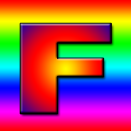
제가 배울 때에는 F 모양의 텍스처가 방향을 바로 판별할 수 있어서 좋은 예제 텍스처라고 배웠습니다.

-  const texture = device.createTexture({
-    label: 'yellow F on red',
-    size: [kTextureWidth, kTextureHeight],
-    format: 'rgba8unorm',
-    usage:
-      GPUTextureUsage.TEXTURE_BINDING |
-      GPUTextureUsage.COPY_DST,
-  });
+  const url = 'resources/images/f-texture.png';
+  const source = await loadImageBitmap(url);
+  const texture = device.createTexture({
+    label: url,
+    format: 'rgba8unorm',
+    size: [source.width, source.height],
+    usage: GPUTextureUsage.TEXTURE_BINDING |
+           GPUTextureUsage.COPY_DST |
+           GPUTextureUsage.RENDER_ATTACHMENT,
+  });
copyExternalImageToTexture를 사용하려면 GPUTextureUsage.COPY_DST 와 GPUTextureUsage.RENDER_ATTACHMENT 플래그를 사용해야 한다는 점을 유의하십시오.
그러면 ImageBitmap를 텍스처에 복사할 수 있습니다.
-  device.queue.writeTexture(
-      { texture },
-      textureData,
-      { bytesPerRow: kTextureWidth * 4 },
-      { width: kTextureWidth, height: kTextureHeight },
-  );
+  device.queue.copyExternalImageToTexture(
+    { source, flipY: true },
+    { texture },
+    { width: source.width, height: source.height },
+  );
copyExternalImageToTexture의 매개변수는 소스(source), 목적지(destination)와 크기입니다.
소스에 대해 flipY: true를 명시하여 로드할 때 텍스처를 뒤집을 것인지를 명시할 수 있습니다.
그러면 바로 동작합니다!
GPU에서 밉 생성하기
이전 글에서 우리는 밉맵도 생성했었습니다.
하지만 이전의 경우에는 우리가 이미지 데이터에 접근하기 쉬운 경우였습니다.
이미지를 로딩할 때는 이미지를 2D 캔버스에 그리고, getImageData를 호출해서 데이터를 얻은 뒤에 밉을 생성하여 업로드해야 합니다.
이러한 과정은 꽤나 오래 걸릴 수 있습니다.
또한 2D 캔버스 렌더링은 내부 구현에 의존적이기 때문에 데이터의 손실이 있을 수도 있습니다.
우리가 밉맵을 생성한 방법은 이중선형 보간이었고, 이는 GPU가 minFilter: linear를 수행하는 것과 동일한 알고리즘입니다.
이러한 기능을 활용하여 GPU상에서 밉 레벨을 생성할 수 있습니다.
이전 글의 밉맵 필터 예제를 수정하여 이미지를 로딩하고 GPU를 사용해 밉을 만들어봅시다.
먼저, 텍스처를 생성하는 코드를 수정하여 밉 레벨을 만들도록 합시다. 몇 개나 생성해야 할지는 아래와 같이 계산하면 됩니다.
  const numMipLevels = (...sizes) => {
    const maxSize = Math.max(...sizes);
    return 1 + Math.log2(maxSize) | 0;
  };
하나 이상의 숫자를 넣고 함수를 호출하면 필요한 밉의 수를 얻을 수 있습니다.
예를들어 numMipLevels(123, 456)를 호출하면 9가 반환됩니다.
- level 0: 123, 456
- level 1: 61, 228
- level 2: 30, 114
- level 3: 15, 57
- level 4: 7, 28
- level 5: 3, 14
- level 6: 1, 7
- level 7: 1, 3
- level 8: 1, 1
9 mip levels
Math.log2는 주어진 숫자가 2의 몇승을 해야 얻어지는지 알려줍니다.
다시 말해 Math.log2(8) = 3인데 23 = 8 이기 때문입니다.
같은 내용을 다른 말로 하면 Math.log2는 어떤 숫자를 2로 몇 번이나 나눌 수 있는지를 알려줍니다.
Math.log2(8)
          8 / 2 = 4
                  4 / 2 = 2
                          2 / 2 = 1
따라서 8은 2로 세 번 나눌 수 있습니다.
이것이 우리가 몇 개의 밉 레벨을 만들어야 하는지를 알게 해줍니다.
Math.log2(largestSize) + 1이고, 1은 밉 레벨 0인 원본 이미지 크기입니다.
이제 올바른 숫자의 밉 레벨 을 만들 수 있습니다.
  const texture = device.createTexture({
    label: url,
    format: 'rgba8unorm',
    mipLevelCount: numMipLevels(source.width, source.height),
    size: [source.width, source.height],
    usage: GPUTextureUsage.TEXTURE_BINDING |
           GPUTextureUsage.COPY_DST |
           GPUTextureUsage.RENDER_ATTACHMENT,
  });
  device.queue.copyExternalImageToTexture(
    { source, flipY: true, },
    { texture },
    { width: source.width, height: source.height },
  );
다음 밉 레벨을 생성하기 위해, 텍스처가 입혀진 사각형을 그릴 것입니다.
이전에 한것과 동일하게 하나의 밉 레벨로부터 다음 레벨의 밉을 minFilter: linear를 사용해 얻습니다.
코드는 아래와 같습니다.
  const generateMips = (() => {
    let sampler;
    let module;
    const pipelineByFormat = {};

    return function generateMips(device, texture) {
      if (!module) {
        module = device.createShaderModule({
          label: 'textured quad shaders for mip level generation',
          code: /* wgsl */ `
            struct VSOutput {
              @builtin(position) position: vec4f,
              @location(0) texcoord: vec2f,
            };

            @vertex fn vs(
              @builtin(vertex_index) vertexIndex : u32
            ) -> VSOutput {
              let pos = array(

                vec2f( 0.0,  0.0),  // center
                vec2f( 1.0,  0.0),  // right, center
                vec2f( 0.0,  1.0),  // center, top

                // 2st triangle
                vec2f( 0.0,  1.0),  // center, top
                vec2f( 1.0,  0.0),  // right, center
                vec2f( 1.0,  1.0),  // right, top
              );

              var vsOutput: VSOutput;
              let xy = pos[vertexIndex];
              vsOutput.position = vec4f(xy * 2.0 - 1.0, 0.0, 1.0);
              vsOutput.texcoord = vec2f(xy.x, 1.0 - xy.y);
              return vsOutput;
            }

            @group(0) @binding(0) var ourSampler: sampler;
            @group(0) @binding(1) var ourTexture: texture_2d<f32>;

            @fragment fn fs(fsInput: VSOutput) -> @location(0) vec4f {
              return textureSample(ourTexture, ourSampler, fsInput.texcoord);
            }
          `,
        });

        sampler = device.createSampler({
          minFilter: 'linear',
        });
      }

      if (!pipelineByFormat[texture.format]) {
        pipelineByFormat[texture.format] = device.createRenderPipeline({
          label: 'mip level generator pipeline',
          layout: 'auto',
          vertex: {
            module,
          },
          fragment: {
            module,
            targets: [{ format: texture.format }],
          },
        });
      }
      const pipeline = pipelineByFormat[texture.format];

      const encoder = device.createCommandEncoder({
        label: 'mip gen encoder',
      });

      for (let baseMipLevel = 1; baseMipLevel < texture.mipLevelCount; ++baseMipLevel) {
        const bindGroup = device.createBindGroup({
          layout: pipeline.getBindGroupLayout(0),
          entries: [
            { binding: 0, resource: sampler },
            {
              binding: 1,
              resource: texture.createView({
                baseMipLevel: baseMipLevel - 1,
                mipLevelCount: 1,
              }),
            },
          ],
        });

        const renderPassDescriptor = {
          label: 'our basic canvas renderPass',
          colorAttachments: [
            {
              view: texture.createView({
                baseMipLevel,
                mipLevelCount: 1,
              }),
              loadOp: 'clear',
              storeOp: 'store',
            },
          ],
        };

        const pass = encoder.beginRenderPass(renderPassDescriptor);
        pass.setPipeline(pipeline);
        pass.setBindGroup(0, bindGroup);
        pass.draw(6);  // call our vertex shader 6 times
        pass.end();
      }
      const commandBuffer = encoder.finish();
      device.queue.submit([commandBuffer]);
    };
  })();
위 코드는 길어 보이지만 지금까지 텍스처 예제에서 사용한 코드와 동일합니다. 바뀐 부분은 아래와 같습니다.
-
module,sampler,pipelineByFormat세 개 변수를 저장할 수 있도록 구현하였습니다.modul과sampler는 이미 설정되었는지를 체크하고, 그렇지 않은 경우GPUSShaderModule와GPUSampler를 만들어 저장하여 나중에 사용할 수 있도록 합니다. -
이전 예제와 거의 동일한 셰이더 두 개가 있습니다. 차이점은 아래 부분 뿐입니다.
 -  vsOutput.position = uni.matrix * vec4f(xy, 0.0, 1.0);
 -  vsOutput.texcoord = xy * vec2f(1, 50);
 +  vsOutput.position = vec4f(xy * 2.0 - 1.0, 0.0, 1.0);
 +  vsOutput.texcoord = vec2f(xy.x, 1.0 - xy.y);
하드코딩된 사각형의 위치 데이터는 0.0에서 1.0 사이라서 이전 예제와 같이 오른쪽 위 사분면만 차지하는 사각형 텍스처가 그려지게 됩니다. 전체 영역에 그려져야 하므로 2를 곱하고 1을 빼서 사각형이 -1,-1에서 +1,+1 영역에 그려지도록 합니다.
또한 텍스처 좌표의 Y값을 뒤집었습니다. 텍스처에 그릴 때 +1, +1이 오른쪽 위지만 우리는 샘플링할 텍스처가 그 위치에 있어야 합니다. 샘플링할 텍스처의 오른쪽 위는 +1, 0입니다.
-
pipelineByFormat객체는 텍스처 포맷에 대한 파이프라인의 맵(map)입니다. 파이프라인이 사용할 포맷을 알아야 하기 때문에 필요합니다. -
특정 포맷에 대해 파리프라인이 있는지 체크하고, 없으면 만듭니다.
    if (!pipelineByFormat[texture.format]) {
      pipelineByFormat[texture.format] = device.createRenderPipeline({
        label: 'mip level generator pipeline',
        layout: 'auto',
        vertex: {
          module,
        },
        fragment: {
          module,
+          targets: [{ format: texture.format }],
        },
      });
    }
    const pipeline = pipelineByFormat[texture.format];
여기서의 유일한 주요 차이점은
target이 텍스처 포맷으로부터 설정된다는 것입니다. 이전에 캔버스에 그릴 때에는presentationFormat를 사용했었습니다. -
마지막으로
texture.createView에 몇몇 매개변수를 사용했습니다.각 밉 레벨에 대해 루프를 돕니다. 그 과정에서 데이터가 그려진 이전 밉에 대한 데이터를 만들고 renderPassDescriptor를 사용해 다음 밉 레벨을 그릴 수 있도록 설정합니다. 그리고 그 특정 밉 레벨에 대한 renderPass를 인코딩합니다. 끝나면 모든 밉이 채워지게 됩니다.
    for (let baseMipLevel = 1; baseMipLevel < texture.mipLevelCount; ++baseMipLevel) {
      const bindGroup = device.createBindGroup({
        layout: pipeline.getBindGroupLayout(0),
        entries: [
          { binding: 0, resource: sampler },
+          {
+            binding: 1,
+            resource: texture.createView({
+              baseMipLevel: baseMipLevel - 1,
+              mipLevelCount: 1,
+            }),
+          },
        ],
      });

      const renderPassDescriptor = {
        label: 'our basic canvas renderPass',
        colorAttachments: [
          {
+            view: texture.createView({baseMipLevel, mipLevelCount: 1}),
            loadOp: 'clear',
            storeOp: 'store',
          },
        ],
      };

      const pass = encoder.beginRenderPass(renderPassDescriptor);
      pass.setPipeline(pipeline);
      pass.setBindGroup(0, bindGroup);
      pass.draw(6);  // call our vertex shader 6 times
      pass.end();
    }

    const commandBuffer = encoder.finish();
    device.queue.submit([commandBuffer]);
이미지를 텍스처로 로딩하고 밉맵을 생성하는 지원 함수를 만들어 사용하기 쉽게 해 봅시다.
아래는 첫번째 밉 레벨을 갱신하고 이미지를 뒤집어주는 함수입니다. 이미지가 밉 레벨이 있다면 생성합니다.
  function copySourceToTexture(device, texture, source, {flipY} = {}) {
    device.queue.copyExternalImageToTexture(
      { source, flipY, },
      { texture },
      { width: source.width, height: source.height },
    );

    if (texture.mipLevelCount > 1) {
      generateMips(device, texture);
    }
  }
아래는 주어진 소스 (ImageBitmap의 경우)로 텍스처를 만들고 위 함수를 호출하여 데이터를 채우는 함수입니다.
  function createTextureFromSource(device, source, options = {}) {
    const texture = device.createTexture({
      format: 'rgba8unorm',
*      mipLevelCount: options.mips ? numMipLevels(source.width, source.height) : 1,
      size: [source.width, source.height],
      usage: GPUTextureUsage.TEXTURE_BINDING |
             GPUTextureUsage.COPY_DST |
             GPUTextureUsage.RENDER_ATTACHMENT,
    });
    copySourceToTexture(device, texture, source, options);
    return texture;
  }
그리고 아래는 주어진 url에 대해 url을 ImageBitmap로 로드하고 이전 함수를 호출하여 텍스처로 만들고 이미지로 그 내용을 채웁니다.
  async function createTextureFromImage(device, url, options) {
    const imgBitmap = await loadImageBitmap(url);
    return createTextureFromSource(device, imgBitmap, options);
  }
이러한 준비 과정으로 인해서 mipmapFilter 예제로부터 수정되는 부분은 아래밖에 없습니다.
-  const textures = [
-    createTextureWithMips(createBlendedMipmap(), 'blended'),
-    createTextureWithMips(createCheckedMipmap(), 'checker'),
-  ];
+  const textures = await Promise.all([
+    await createTextureFromImage(device,
+        'resources/images/f-texture.png', {mips: true, flipY: false}),
+    await createTextureFromImage(device,
+        'resources/images/coins.jpg', {mips: true}),
+    await createTextureFromImage(device,
+        'resources/images/Granite_paving_tileable_512x512.jpeg', {mips: true}),
+  ]);
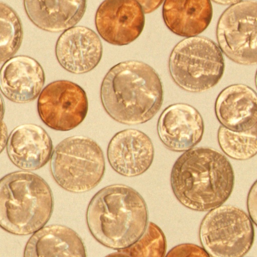
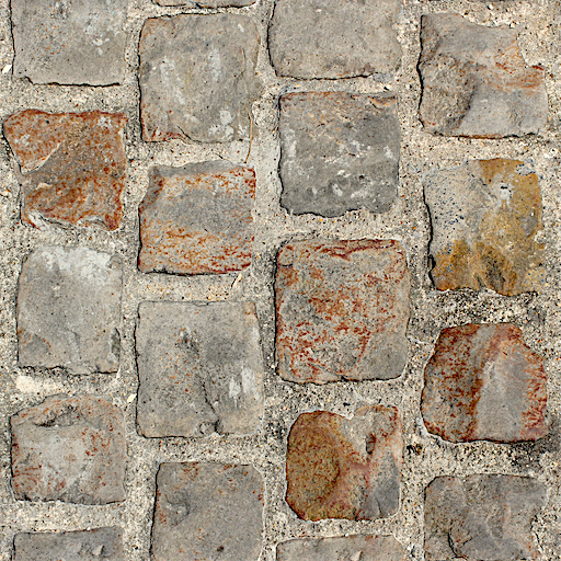
위 코드는 F 텍스처와 아래의 두 타일(tile) 텍스처를 로드합니다.
결과는 아래와 같습니다.
캔버스 로딩
copyExternalImageToTexture는 다른 소스도 받을 수 있습니다.
다른 소스로는 HTMLCanvasElement가 있습니다.
이를 사용하여 2D 캔버스에 무언가를 그리고 그 결과를 WebGPU 텍스처로 받을 수 있습니다.
WebGPU를 사용해서 텍스처에 무언가를 그리고 그 텍스처를 무언가를 렌더링하기 위해 사용할 수도 있습니다.
사실 방금 전까지 한 것이 이런 내용인데, 밉 레벨에 렌더링을 수행하고 그 밉 레벨을 텍스처 어태치먼트로 해서 다음 밉 레벨을 렌더링하였습니다.
하지만 2D 캔버스를 사용하면 좀 더 편하게 할 수 있는 작업도 있습니다. 2D 캔버스는 상대적으로 고수준 API를 제공합니다.
우선 캔버스 애니메이션을 만들어 봅시다.
const size = 256;
const half = size / 2;

const ctx = document.createElement('canvas').getContext('2d');
ctx.canvas.width = size;
ctx.canvas.height = size;

const hsl = (h, s, l) => `hsl(${h * 360 | 0}, ${s * 100}%, ${l * 100 | 0}%)`;

function update2DCanvas(time) {
  time *= 0.0001;
  ctx.clearRect(0, 0, size, size);
  ctx.save();
  ctx.translate(half, half);
  const num = 20;
  for (let i = 0; i < num; ++i) {
    ctx.fillStyle = hsl(i / num * 0.2 + time * 0.1, 1, i % 2 * 0.5);
    ctx.fillRect(-half, -half, size, size);
    ctx.rotate(time * 0.5);
    ctx.scale(0.85, 0.85);
    ctx.translate(size / 16, 0);
  }
  ctx.restore();
}

function render(time) {
  update2DCanvas(time);
  requestAnimationFrame(render);
}
requestAnimationFrame(render);
이 캔버스를 WebGPU로 로드하기 위해서는 이전 예제에서 몇 가지만 수정하면 됩니다.
우선 적절한 크기의 텍스처를 만들어야 합니다. 가장 쉬운 방법은 이전에 사용한 코드와 동일한 코드를 사용하는 것입니다.
+  const texture = createTextureFromSource(device, ctx.canvas, {mips: true});

  const textures = await Promise.all([
-    await createTextureFromImage(device,
-        'resources/images/f-texture.png', {mips: true, flipY: false}),
-    await createTextureFromImage(device,
-        'resources/images/coins.jpg', {mips: true}),
-    await createTextureFromImage(device,
-        'resources/images/Granite_paving_tileable_512x512.jpeg', {mips: true}),
+    texture,
  ]);
그리고 requestAnimationFrame 루프로 수정해서 2D 캔버스를 갱신하고 WebGPU로 업로드하도록 합니다.
-  function render() {
+  function render(time) {
+    update2DCanvas(time);
+    copySourceToTexture(device, texture, ctx.canvas);

     ...


    requestAnimationFrame(render);
  }
  requestAnimationFrame(render);

  const observer = new ResizeObserver(entries => {
    for (const entry of entries) {
      const canvas = entry.target;
      const width = entry.contentBoxSize[0].inlineSize;
      const height = entry.contentBoxSize[0].blockSize;
      canvas.width = Math.max(1, Math.min(width, device.limits.maxTextureDimension2D));
      canvas.height = Math.max(1, Math.min(height, device.limits.maxTextureDimension2D));
-      render();
    }
  });
  observer.observe(canvas);

  canvas.addEventListener('click', () => {
    texNdx = (texNdx + 1) % textures.length;
-    render();
  });
이렇게 하면 캔버스를 업로드하면서도 이에 대한 밉 레벨들이 만들어집니다.
비디오 로딩
비디오를 이러한 방식으로 로딩하는 것도 다를 바 없습니다.
<video> 엘리먼트(element)를 만들고 이전 예제에서 캔버스를 전달한것과 동일한 함수에 전달합니다.
그러면 조금만 수정하면 제대로 동작합니다.
비디오는 아래와 같습니다.
ImageBitmap과 HTMLCanvasElement는 너비와 높이를 width와 height 속성으로 가지고 있었지만 HTMLVideoElement의 경우 videoWidth와 videoHeight 속성입니다.
따라서 이 차이를 반영할 수 있게 코드를 수정합시다.
+  function getSourceSize(source) {
+    return [
+      source.videoWidth || source.width,
+      source.videoHeight || source.height,
+    ];
+  }

  function copySourceToTexture(device, texture, source, {flipY} = {}) {
    device.queue.copyExternalImageToTexture(
      { source, flipY, },
      { texture },
-      { width: source.width, height: source.height },
+      getSourceSize(source),
    );

    if (texture.mipLevelCount > 1) {
      generateMips(device, texture);
    }
  }

  function createTextureFromSource(device, source, options = {}) {
+    const size = getSourceSize(source);
    const texture = device.createTexture({
      format: 'rgba8unorm',
-      mipLevelCount: options.mips ? numMipLevels(source.width, source.height) : 1,
-      size: [source.width, source.height],
+      mipLevelCount: options.mips ? numMipLevels(...size) : 1,
+      size,
      usage: GPUTextureUsage.TEXTURE_BINDING |
             GPUTextureUsage.COPY_DST |
             GPUTextureUsage.RENDER_ATTACHMENT,
    });
    copySourceToTexture(device, texture, source, options);
    return texture;
  }
그리고 비디오 엘리먼트를 만듭니다.
  const video = document.createElement('video');
  video.muted = true;
  video.loop = true;
  video.preload = 'auto';
  video.src = 'resources/videos/Golden_retriever_swimming_the_doggy_paddle-360-no-audio.webm';

  const texture = createTextureFromSource(device, video, {mips: true});
그리고 렌더링 시점에 갱신합니다.
-  function render(time) {
-    update2DCanvas(time);
-    copySourceToTexture(device, texture, ctx.canvas);
+  function render() {
+    copySourceToTexture(device, texture, video);
비디오를 사용할 때 까다로운 점 중 하나는 WebGPU로 전달하기 전에 재생이 시작될 때까지 기다려야 한다는 점입니다.
최근 브라우저에서는 video.requestVideoFrameCallback를 호출하여 할 수 있습니다.
새로운 프레임이 사용 가능해지면 호출되므로 이를 사용해 최소한 하나의 프레임이 사용 가능한지 확인할 수 있습니다.
그렇게 확인하는 것의 대안으로, 잠시 시간을 보내면서 (프레임이 사용가능해지기를) 기도하는 것입니다🙏. 안타깝게도 오래된 브라우저에서는 언제 비디오 데이터가 사용할 준비가 되었는지 알기 어렵습니다.😅
+  function startPlayingAndWaitForVideo(video) {
+    return new Promise((resolve, reject) => {
+      video.addEventListener('error', reject);
+      if ('requestVideoFrameCallback' in video) {
+        video.requestVideoFrameCallback(resolve);
+      } else {
+        const timeWatcher = () => {
+          if (video.currentTime > 0) {
+            resolve();
+          } else {
+            requestAnimationFrame(timeWatcher);
+          }
+        };
+        timeWatcher();
+      }
+      video.play().catch(reject);
+    });
+  }

  const video = document.createElement('video');
  video.muted = true;
  video.loop = true;
  video.preload = 'auto';
  video.src = 'resources/videos/Golden_retriever_swimming_the_doggy_paddle-360-no-audio.webm';
+  await startPlayingAndWaitForVideo(video);

  const texture = createTextureFromSource(device, video, {mips: true});
또다른 까다로운점은 비디오 재생을 시작하기전에 사용자가 웹페이지와 인터랙션 하기를 기다려야 한다는 점입니다 [1]. 재생 버튼을 HTML에 추가합시다.
  <body>
    <canvas></canvas>
+    <div id="start">
+      <div>▶️</div>
+    </div>
  </body>
가운에 정렬을 위해 CSS도 수정합니다.
#start {
  position: fixed;
  left: 0;
  top: 0;
  width: 100%;
  height: 100%;
  display: flex;
  justify-content: center;
  align-items: center;
}
#start>div {
  font-size: 200px;
  cursor: pointer;
}
클릭될 때까지 기다린 이후 숨기는 기능을 추가합니다.
+  function waitForClick() {
+    return new Promise(resolve => {
+      window.addEventListener(
+        'click',
+        () => {
+          document.querySelector('#start').style.display = 'none';
+          resolve();
+        },
+        { once: true });
+    });
+  }

  const video = document.createElement('video');
  video.muted = true;
  video.loop = true;
  video.preload = 'auto';
  video.src = 'resources/videos/Golden_retriever_swimming_the_doggy_paddle-360-no-audio.webm';
+  await waitForClick();
  await startPlayingAndWaitForVideo(video);

  const texture = createTextureFromSource(device, video, {mips: true});
비디오를 정지하는 기능도 추가합니다.
  const video = document.createElement('video');
  video.muted = true;
  video.loop = true;
  video.preload = 'auto';
  video.src = 'resources/videos/pexels-anna-bondarenko-5534310 (540p).mp4'; /* webgpufundamentals: url */
  await waitForClick();
  await startPlayingAndWaitForVideo(video);

+  canvas.addEventListener('click', () => {
+    if (video.paused) {
+      video.play();
+    } else {
+      video.pause();
+    }
+  });
이렇게 하면 텍스처에 비디오가 보일겁니다.
최적화 방안 중 하나는 비디오가 변했을 때만 텍스처를 업데이트하는 것입니다.
예시는 아래와 같습니다.
  const video = document.createElement('video');
  video.muted = true;
  video.loop = true;
  video.preload = 'auto';
  video.src = 'resources/videos/Golden_retriever_swimming_the_doggy_paddle-360-no-audio.webm';
  await waitForClick();
  await startPlayingAndWaitForVideo(video);

+  let alwaysUpdateVideo = !('requestVideoFrameCallback' in video);
+  let haveNewVideoFrame = false;
+  if (!alwaysUpdateVideo) {
+    function recordHaveNewFrame() {
+      haveNewVideoFrame = true;
+      video.requestVideoFrameCallback(recordHaveNewFrame);
+    }
+    video.requestVideoFrameCallback(recordHaveNewFrame);
+  }

  ...

  function render() {
+    if (alwaysUpdateVideo || haveNewVideoFrame) {
+      haveNewVideoFrame = false;
      copySourceToTexture(device, texture, video);
+    }

    ...
이렇게 하면 새로운 프레임에 대해서만 비디오를 업데이트합니다. 예를 들어 디스플레이 주사율이 120프레임인 장치에서는 1초에 120번씩 프레임이 그려지므로 애니메이션, 카메라 움직임 등이 더 부드러울 것입니다. 하지만 텍스처는 그 자신의 프레임 레이트(예를들어 30fps)로만 업데이트 될것입니다.
하지만! WebGPU는 효율적인 비디오 사용을 위한 특수 기능을 지원합니다
이러한 내용은 다른 글에서 다룰 것입니다.
위에서 device.query.copyExternalImageToTexture를 사용하면 실제로는 사본을 만드는 것입니다.
그리고 복사에는 시간이 걸립니다.
예를 들어 4K 비디오의 일반적인 해상도는 3840 x 2160인데, rgba8unorm 포맷의 경우 31MB의 데이터가 프레임마다 복사되어야 한다는 뜻입니다.
외부(External) 텍스처를 사용하면 (복사 없이) 비디오 데이터를 직접 사용 가능하지만 다른 방법을 사용해야 하고 제약 사항이 좀 있습니다.
텍스처 아틀라스(Atlas)
위 예제에서, 우리는 텍스처를 사용해서 무언가를 그리기 위해서는 우선 텍스처를 만들고, 데이터를 넣은 후에 샘플러와 함께 바인드그룹에 바인드하고, 셰이더에서 참조해야 한다는 것을 배웠습니다. 어떤 물체에 여러 개의 서로 다른 텍스처를 사용하려면 어떻게 해야 할까요? 예를 들어 의자가 있어서 다리와 등받이는 나무로 만들어지고 쿠션은 천으로 만들어 졌다면 말이죠.
또는 자동차 모델이 있어서 타이어는 고무이고 차체에는 페인트가 칠해져 있고, 범퍼와 휠캡은 크롬 도금되어 있는 경우도 있겠죠.
별다른 해법이 없다면 의자의 경우 나무 텍스처로 나무 부분을 한번, 천 텍스처로 쿠션 부분 한번 해서 두 번을 그려야 한다고 생각하실 수 있습니다. 자동차의 경우 두 번 이상일겁니다. 타이어 한번, 차체 한번 범퍼 한번 등등 말이죠.
이렇게 되면 모든 물체가 여러 번의 드로우콜을 필요로 하기 때문에 느려지게 됩니다. 이는 셰이더에 여러 입력(2,3,4 텍스처)을 사용하고 각각에 대해 텍스처 좌표를 사용하여 해결할 수도 있지만 이는 유연성이 떨어지는데다, 네 개 텍스처를 모두 읽고 그 값들 중 하나를 선택하도록 코드를 작성해야 한다는 단점이 있습니다.
이러한 문제를 해결하는 가장 일반적인 방법은 텍스처 아틀라스(Texture Atlas)라는 것을 사용하는 것입니다. 텍스처 아틀라스는 여러 이미지가 들어있는 텍스처를 부르는 멋있는 이름입니다. 그리고 텍스처 좌표를 사용해서 어느 부분이 어디에 사용될지 결정합니다.
육면체(cube)에 아래 여섯 개의 이미지를 입혀봅시다.
 | 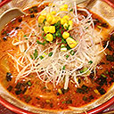 |
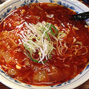 | 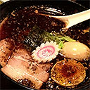 |
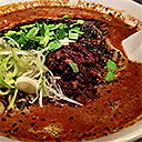 | 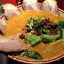 |
포토샵이나 Photopea와 같은 이미지 편집 소프트웨어를 사용해 여섯 개의 이미지를 하나의 이미지에 넣을 수 있습니다.
그리고 큐브의 각 면에 해당하는 이미지를 선택할 수 있도록 텍스처 좌표를 제공하는 큐브들 만듭니다. 간단하게 하기 위해 여섯 개의 이미지를 4x2의 형태로 배치하였습니다. 이렇게 하면 각 사각형에 대한 텍스처 좌표의 계산이 간단해집니다.
일반적으로 텍스처 좌표의 0,0이 왼쪽 아래인 경우가 많이 때문에 위 다이어그램이 헷갈릴 수 있습니다. 사실 “아래” 라는 것은 없습니다. 단지 텍스처 좌표 0,0은 텍스처의 첫 번째 데이터를 참조하는 값일 뿐입니다. 위의 경우 텍스처의 첫 번째 데이터가 이미지의 오른쪽 위가 되었을 뿐입니다. 0,0이 왼쪽 아래라는 것을 고수하고 싶다면 아래와 같이 보시면 됩니다. 이렇게 해도 좌표는 같습니다.
아래는 큐브에 대한 정점 위치와 텍스처 좌표 입니다.
function createCubeVertices() {
  const vertexData = new Float32Array([
     //  position   |  texture coordinate
     //-------------+----------------------
     // front face     select the top left image
    -1,  1,  1,        0   , 0  ,
    -1, -1,  1,        0   , 0.5,
     1,  1,  1,        0.25, 0  ,
     1, -1,  1,        0.25, 0.5,
     // right face     select the top middle image
     1,  1, -1,        0.25, 0  ,
     1,  1,  1,        0.5 , 0  ,
     1, -1, -1,        0.25, 0.5,
     1, -1,  1,        0.5 , 0.5,
     // back face      select to top right image
     1,  1, -1,        0.5 , 0  ,
     1, -1, -1,        0.5 , 0.5,
    -1,  1, -1,        0.75, 0  ,
    -1, -1, -1,        0.75, 0.5,
    // left face       select the bottom left image
    -1,  1,  1,        0   , 0.5,
    -1,  1, -1,        0.25, 0.5,
    -1, -1,  1,        0   , 1  ,
    -1, -1, -1,        0.25, 1  ,
    // bottom face     select the bottom middle image
     1, -1,  1,        0.25, 0.5,
    -1, -1,  1,        0.5 , 0.5,
     1, -1, -1,        0.25, 1  ,
    -1, -1, -1,        0.5 , 1  ,
    // top face        select the bottom right image
    -1,  1,  1,        0.5 , 0.5,
     1,  1,  1,        0.75, 0.5,
    -1,  1, -1,        0.5 , 1  ,
     1,  1, -1,        0.75, 1  ,

  ]);

  const indexData = new Uint16Array([
     0,  1,  2,  2,  1,  3,  // front
     4,  5,  6,  6,  5,  7,  // right
     8,  9, 10, 10,  9, 11,  // back
    12, 13, 14, 14, 13, 15,  // left
    16, 17, 18, 18, 17, 19,  // bottom
    20, 21, 22, 22, 21, 23,  // top
  ]);

  return {
    vertexData,
    indexData,
    numVertices: indexData.length,
  };
}
이 예제는 카메라에 관한 글의 예제에서부터 시작합니다. 해당 글을 아직 읽지 않으셨으면 3D에 관한 글의 일부이므로, 읽어 보시길 바랍니다. 지금 중요한 것은 이전에 했던 것처럼 정점 셰이더에서 위치와 텍스처 좌표를 출력할 것이고 이를 사용하여 프래그맨트 셰이더에서 텍스처로부터 값을 얻어올 때 사용할 것이라는 사실입니다. 아래는 카메라 예제에서부터 수정된 셰이더입니다.
struct Uniforms {
  matrix: mat4x4f,
};

struct Vertex {
  @location(0) position: vec4f,
-  @location(1) color: vec4f,
+  @location(1) texcoord: vec2f,
};

struct VSOutput {
  @builtin(position) position: vec4f,
-  @location(0) color: vec4f,
+  @location(0) texcoord: vec2f,
};

@group(0) @binding(0) var<uniform> uni: Uniforms;
+@group(0) @binding(1) var ourSampler: sampler;
+@group(0) @binding(2) var ourTexture: texture_2d<f32>;

@vertex fn vs(vert: Vertex) -> VSOutput {
  var vsOut: VSOutput;
  vsOut.position = uni.matrix * vert.position;
-  vsOut.color = vert.color;
+  vsOut.texcoord = vert.texcoord;
  return vsOut;
}

@fragment fn fs(vsOut: VSOutput) -> @location(0) vec4f {
-  return vsOut.color;
+  return textureSample(ourTexture, ourSampler, vsOut.texcoord);
}
바뀐것은 정점별 색상에서 정점별 텍스처 좌표로 수정한 것이고, 그 텍스처 좌표를 프래그먼트 셰이더로 넘긴 것입니다. 그리고 프래그먼트 셰이더에서 이를 사용하였습니다.
자바스크립트 부분에서는 색상값을 얻어오는 것에서 텍스처 좌표를 얻어오는 것으로 파이프라인을 수정합니다.
  const pipeline = device.createRenderPipeline({
    label: '2 attributes',
    layout: 'auto',
    vertex: {
      module,
      buffers: [
        {
-          arrayStride: (4) * 4, // (3) floats 4 bytes each + one 4 byte color
+          arrayStride: (3 + 2) * 4, // (3+2) floats 4 bytes each
          attributes: [
            {shaderLocation: 0, offset: 0, format: 'float32x3'},  // position
-            {shaderLocation: 1, offset: 12, format: 'unorm8x4'},  // color
+            {shaderLocation: 1, offset: 12, format: 'float32x2'},  // texcoord
          ],
        },
      ],
    },
    fragment: {
      module,
      targets: [{ format: presentationFormat }],
    },
    primitive: {
      cullMode: 'back',
    },
    depthStencil: {
      depthWriteEnabled: true,
      depthCompare: 'less',
      format: 'depth24plus',
    },
  });
정점 버퍼에 관한 글에서처럼 데이터를 가볍게 하기위해 인덱스를 사용합니다.
-  const { vertexData, numVertices } = createFVertices();
+  const { vertexData, indexData, numVertices } = createCubeVertices();
  const vertexBuffer = device.createBuffer({
    label: 'vertex buffer vertices',
    size: vertexData.byteLength,
    usage: GPUBufferUsage.VERTEX | GPUBufferUsage.COPY_DST,
  });
  device.queue.writeBuffer(vertexBuffer, 0, vertexData);

+  const indexBuffer = device.createBuffer({
+    label: 'index buffer',
+    size: indexData.byteLength,
+    usage: GPUBufferUsage.INDEX | GPUBufferUsage.COPY_DST,
+  });
+  device.queue.writeBuffer(indexBuffer, 0, indexData);
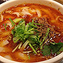
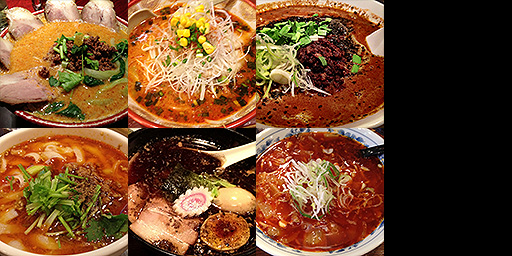
텍스처 로딩과 밉 생성에 관한 코드를 복사해서 여기에 가져옵니다. 그리고 해당 코드를 사용해 텍스처 아틀라스 이미지를 로드합니다. 또한 샘플러를 만들고 이를 바인드 그룹에 추가합니다.
+  const texture = await createTextureFromImage(device,
+      'resources/images/noodles.jpg', {mips: true, flipY: false});
+
+  const sampler = device.createSampler({
+    magFilter: 'linear',
+    minFilter: 'linear',
+    mipmapFilter: 'linear',
+  });

  const bindGroup = device.createBindGroup({
    label: 'bind group for object',
    layout: pipeline.getBindGroupLayout(0),
    entries: [
      { binding: 0, resource: uniformBuffer },
+      { binding: 1, resource: sampler },
+      { binding: 2, resource: texture },
    ],
  });
3차원 그리지를 위한 행렬들을 설정합니다. (다시 말씀드리지만 이러한 내용들은 카메라에 관한 글의 3차원 수학 부분을 참고하세요.)
  const degToRad = d => d * Math.PI / 180;

  const settings = {
    rotation: [degToRad(20), degToRad(25), degToRad(0)],
  };

  const radToDegOptions = { min: -360, max: 360, step: 1, converters: GUI.converters.radToDeg };

  const gui = new GUI();
  gui.onChange(render);
  gui.add(settings.rotation, '0', radToDegOptions).name('rotation.x');
  gui.add(settings.rotation, '1', radToDegOptions).name('rotation.y');
  gui.add(settings.rotation, '2', radToDegOptions).name('rotation.z');

  ...

  function render() {

    ...

    const aspect = canvas.clientWidth / canvas.clientHeight;
    mat4.perspective(
        60 * Math.PI / 180,
        aspect,
        0.1,      // zNear
        10,      // zFar
        matrixValue,
    );
    const view = mat4.lookAt(
      [0, 1, 5],  // camera position
      [0, 0, 0],  // target
      [0, 1, 0],  // up
    );
    mat4.multiply(matrixValue, view, matrixValue);
    mat4.rotateX(matrixValue, settings.rotation[0], matrixValue);
    mat4.rotateY(matrixValue, settings.rotation[1], matrixValue);
    mat4.rotateZ(matrixValue, settings.rotation[2], matrixValue);

    // upload the uniform values to the uniform buffer
    device.queue.writeBuffer(uniformBuffer, 0, uniformValues);
그리고 렌더링 시점에, 인덱스를 사용해 그립니다.
    const encoder = device.createCommandEncoder();
    const pass = encoder.beginRenderPass(renderPassDescriptor);
    pass.setPipeline(pipeline);
    pass.setVertexBuffer(0, vertexBuffer);
+    pass.setIndexBuffer(indexBuffer, 'uint16');

    ...

    pass.setBindGroup(0, bindGroup);
-    pass.draw(numVertices);
+    pass.drawIndexed(numVertices);

    pass.end();
이렇게 하면 각 면에 다른 이미지가 있는 큐브를, 단일 텍스처를 사용하여 그릴 수 있습니다.
하나의 텍스처만 로드하면 되기 때문에 텍스처 아틀라스를 사용하면 좋습니다. 셰이더는 하나의 텍스처만 참조하면 되기 때문에 간단하고, 이미지가 여러 장으로 나뉜 상황에서처럼 텍스처별로 드로우 콜을 호출하는 대신 한 번의 드로우 콜로 물체를 그릴 수 있게 됩니다.
비디오를 얻는 방법도 여러 방법이 있는데 대개는 오디오를 끄고, 사용자가 플레이 버튼을 누르기까지 기다리지 않고 자동재생하는 방법입니다. 이러한 방법은 시간에 따라 바뀌는 관계로 여기서는 사용하지 않을 것입니다. ↩︎