WebGPU コンピュートシェーダー - 画像ヒストグラム パート2
前の記事では、JavaScriptで画像ヒストグラムを作成する方法を説明し、それをWebGPUを使用するように変換し、最適化のいくつかのステップを経験しました。
それを使って、もう少しやってみましょう。
4つのヒストグラムを一度に生成する
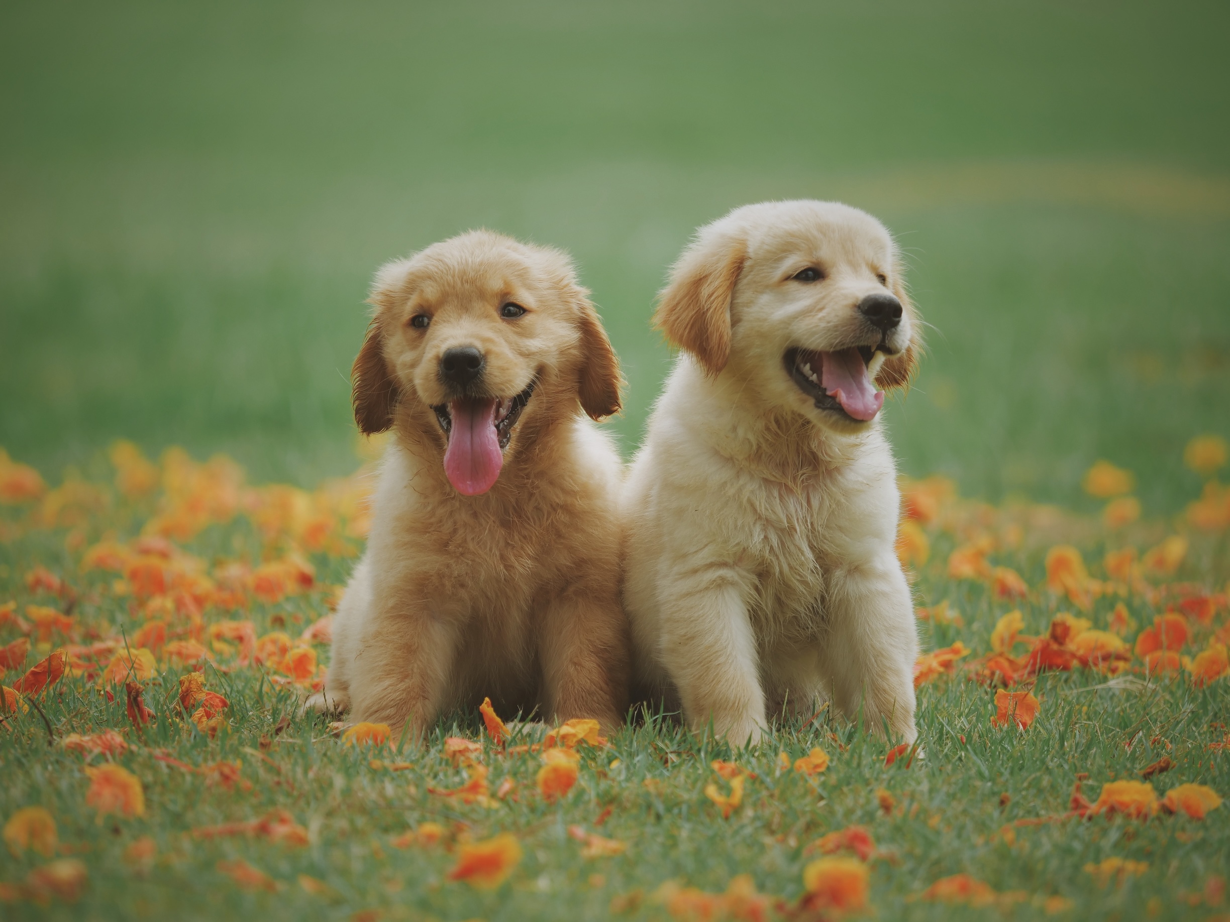
このような画像が与えられたとします。
複数のヒストグラムを生成するのが一般的です。
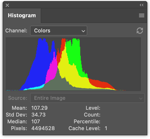
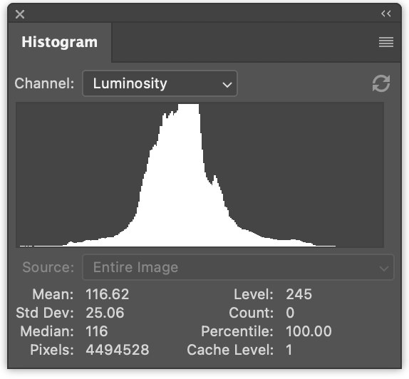
左側には、赤の値、緑の値、青の値の3つのヒストグラムがあります。それらは重なり合って描画されています。右側には、前の記事で生成したような輝度ヒストグラムがあります。
一度に4つすべてを生成するのは、ほんのわずかな変更です。
JavaScriptでは、一度に4つのヒストグラムを生成するための変更は次のとおりです。
function computeHistogram(numBins, imgData) {
  const {width, height, data} = imgData;
-  const bins = new Array(numBins).fill(0);
+  const bins = new Array(numBins * 4).fill(0);
  for (let y = 0; y < height; ++y) {
    for (let x = 0; x < width; ++x) {
      const offset = (y * width + x) * 4;

-      const r = data[offset + 0] / 255;
-      const g = data[offset + 1] / 255;
-      const b = data[offset + 2] / 255;
-      const v = srgbLuminance(r, g, b);
-
-      const bin = Math.min(numBins - 1, v * numBins) | 0;
-      ++bins[bin];

+       for (const ch = 0; ch < 4; ++ch) {
+          const v = ch < 3
+             ? data[offset + ch] / 255
+             : srgbLuminance(data[offset + 0] / 255,
+                             data[offset + 1] / 255,
+                             data[offset + 2] / 255);
+          const bin = Math.min(numBins - 1, v * numBins) | 0;
+          ++bins[bin * 4 + ch];
+       }
    }
  }
  return bins;
}
これにより、ヒストグラムがr, g, b, l, r, g, b, l, r, g, b, l …のようにインターリーブされて生成されます。
次のようにレンダリングするようにコードを更新できます。
function drawHistogram(histogram, numEntries, channels, height = 100) {
-  const numBins = histogram.length;
-  const max = Math.max(...histogram);
-  const scale = Math.max(1 / max);//, 0.2 * numBins / numEntries);
+  // 各チャンネルの最大値を見つけます
+  const numBins = histogram.length / 4;
+  const max = [0, 0, 0, 0];
+  histogram.forEach((v, ndx) => {
+    const ch = ndx % 4;
+    max[ch] = Math.max(max[ch], v);
+  });
+  const scale = max.map(max => Math.max(1 / max, 0.2 * numBins / numEntries));

  const canvas = document.createElement('canvas');
  canvas.width = numBins;
  canvas.height = height;
  document.body.appendChild(canvas);
  const ctx = canvas.getContext('2d');

+  const colors = [
+    'rgb(255, 0, 0)',
+    'rgb(0, 255, 0)',
+    'rgb(0, 0, 255)',
+    'rgb(255, 255, 255)',
+  ];

-  ctx.fillStyle = '#fff';
+  ctx.globalCompositeOperation = 'screen';

  for (let x = 0; x < numBins; ++x) {
-    const v = histogram[x] * scale * height;
-    ctx.fillRect(x, height - v, 1, v);
+    const offset = x * 4;
+    for (const ch of channels) {
+      const v = histogram[offset + ch] * scale[ch] * height;
+      ctx.fillStyle = colors[ch];
+      ctx.fillRect(x, height - v, 1, v);
+    }
  }
}
そして、その関数を2回呼び出します。1回はカラーヒストグラムをレンダリングするため、もう1回は輝度ヒストグラムのためです。
  const histogram = computeHistogram(numBins, imgData);

  showImageBitmap(imgBitmap);

+  // 赤、緑、青のチャンネルを描画します
  const numEntries = imgData.width * imgData.height;
-  drawHistogram(histogram, numEntries);
+ drawHistogram(histogram, numEntries, [0, 1, 2]);
+
+  // 輝度チャンネルを描画します
+  drawHistogram(histogram, numEntries, [3]);
そして、これらの結果が得られます。
WGSLの例に同じことを行うのはさらに簡単です。
たとえば、遅すぎた最初の例は、次のように変更されます。
-@group(0) @binding(0) var<storage, read_write> bins: array<u32>;
+@group(0) @binding(0) var<storage, read_write> bins: array<vec4u>;
@group(0) @binding(1) var ourTexture: texture_2d<f32>;

// from: https://www.w3.org/WAI/GL/wiki/Relative_luminance
const kSRGBLuminanceFactors = vec3f(0.2126, 0.7152, 0.0722);
fn srgbLuminance(color: vec3f) -> f32 {
  return saturate(dot(color, kSRGBLuminanceFactors));
}

@compute @workgroup_size(1, 1, 1) fn cs() {
  let size = textureDimensions(ourTexture, 0);
  let numBins = f32(arrayLength(&bins));
  let lastBinIndex = u32(numBins - 1);
  for (var y = 0u; y < size.y; y++) {
    for (var x = 0u; x < size.x; x++) {
      let position = vec2u(x, y);
-      let color = textureLoad(ourTexture, position, 0);
-      let v = srgbLuminance(color.rgb);
-      let bin = min(u32(v * numBins), lastBinIndex);
-      bins[bin] += 1;
+      var channels = textureLoad(ourTexture, position, 0);
+      channels.w = srgbLuminance(channels.rgb);
+      for (var ch = 0; ch < 4; ch++) {
+        let v = channels[ch];
+        let bin = min(u32(v * numBins), lastBinIndex);
+        bins[bin][ch] += 1;
+      }
    }
  }
}
binsをarray<u32>からarray<vec4u>に変更して、4つのチャンネルすべてのためのスペースを確保する必要がありました。
次に、テクスチャから色を取り出し、輝度を計算してchannelsのw要素に入れました。
  var channels = textureLoad(ourTexture, position, 0);
  channels.w = srgbLuminance(channels.rgb);
こうすることで、4つのチャンネルをループして正しいビンをインクリメントするだけで済みます。
必要なもう1つの変更は、バッファに4倍のメモリを割り当てることです。
  const histogramBuffer = device.createBuffer({
-    size: numBins * 4, // 256エントリ * 4バイト/u32
+    size: 256 * 4 * 4, // 256エントリ * 4 (rgba) * 4バイト/u32
    usage: GPUBufferUsage.STORAGE | GPUBufferUsage.COPY_SRC,
  });
そして、これが4つのヒストグラムを生成する遅いWebGPUバージョンです。
最速バージョンに同様の変更を加えます。
const chunkWidth = 256;
const chunkHeight = 1;
const chunkSize = chunkWidth * chunkHeight;
-var<workgroup> bins: array<atomic<u32>, chunkSize>;
-@group(0) @binding(0) var<storage, read_write> chunks: array<array<u32, chunkSize>>;
+var<workgroup> bins: array<array<atomic<u32>, 4>, chunkSize>;
+@group(0) @binding(0) var<storage, read_write> chunks: array<array<vec4u, chunkSize>>;
@group(0) @binding(1) var ourTexture: texture_2d<f32>;

const kSRGBLuminanceFactors = vec3f(0.2126, 0.7152, 0.0722);
fn srgbLuminance(color: vec3f) -> f32 {
  return saturate(dot(color, kSRGBLuminanceFactors));
}

@compute @workgroup_size(chunkWidth, chunkHeight, 1)
fn cs(
  @builtin(workgroup_id) workgroup_id: vec3u,
  @builtin(local_invocation_id) local_invocation_id: vec3u,
) {
  let size = textureDimensions(ourTexture, 0);
  let position = workgroup_id.xy * vec2u(chunkWidth, chunkHeight) +
                 local_invocation_id.xy;
  if (all(position < size)) {
    let numBins = f32(chunkSize);
    let lastBinIndex = u32(numBins - 1);
-    let color = textureLoad(ourTexture, position, 0);
-    let v = srgbLuminance(color.rgb);
-    let bin = min(u32(v * numBins), lastBinIndex);
-    atomicAdd(&bins[bin], 1u);
+    var channels = textureLoad(ourTexture, position, 0);
+    channels.w = srgbLuminance(channels.rgb);
+    for (var ch = 0; ch < 4; ch++) {
+      let v = channels[ch];
+      let bin = min(u32(v * numBins), lastBinIndex);
+      atomicAdd(&bins[bin][ch], 1u);
+    }
  }

  workgroupBarrier();

  let chunksAcross = (size.x + chunkWidth - 1) / chunkWidth;
  let chunk = workgroup_id.y * chunksAcross + workgroup_id.x;
  let bin = local_invocation_id.y * chunkWidth + local_invocation_id.x;

-  chunks[chunk][bin] = atomicLoad(&bins[bin]);
+  chunks[chunk][bin] = vec4u(
+    atomicLoad(&bins[bin][0]),
+    atomicLoad(&bins[bin][1]),
+    atomicLoad(&bins[bin][2]),
+    atomicLoad(&bins[bin][3]),
+  );
}
そして、リデュースシェーダー用です。
const chunkWidth = 256;
const chunkHeight = 1;
const chunkSize = chunkWidth * chunkHeight;

struct Uniforms {
  stride: u32,
};

-@group(0) @binding(0) var<storage, read_write> chunks: array<array<u32, chunkSize>>;
+@group(0) @binding(0) var<storage, read_write> chunks: array<array<vec4u, chunkSize>>;
@group(0) @binding(1) var<uniform> uni: Uniforms;

@compute @workgroup_size(chunkSize, 1, 1) fn cs(
  @builtin(local_invocation_id) local_invocation_id: vec3u,
  @builtin(workgroup_id) workgroup_id: vec3u,
) {
  let chunk0 = workgroup_id.x * uni.stride * 2;
  let chunk1 = chunk0 + uni.stride;

  let sum = chunks[chunk0][local_invocation_id.x] +
            chunks[chunk1][local_invocation_id.x];
  chunks[chunk0][local_invocation_id.x] = sum;
}
前の例と同様に、バッファサイズを増やす必要があります。
  const chunksBuffer = device.createBuffer({
-    size: numChunks * chunkSize * 4,  // 4バイト/u32
+    size: numChunks * chunkSize * 4 * 4,  // 16バイト/vec4u
    usage: GPUBufferUsage.STORAGE | GPUBufferUsage.COPY_SRC,
  });

  const resultBuffer = device.createBuffer({
-    size: chunkSize * 4,
+    size: chunkSize * 4 * 4,
    usage: GPUBufferUsage.COPY_DST | GPUBufferUsage.MAP_READ,
  });
以上です。
前の記事で試した他の2つのステップがありました。1つはピクセルごとに1つのワークグループを使用し、もう1つはビンをリデュースする代わりにビンごとに1つの呼び出しでチャンクを合計しました。
これらの4チャンネルバージョンをテストして得られたタイミング情報をいくつか紹介します。
前の記事の1チャンネルバージョンと比較できます。
GPUでヒストグラムを描画する
GPUでヒストグラムを描画しましょう。JavaScriptでは、canvas 2D APIを使用して、各ビンに対して1×高さの長方形を描画しましたが、これは非常に簡単でした。WebGPUでも同じことができますが、ヒストグラムを描画するという特定の問題に対しては、より良いアプローチがあると思います。
代わりに、長方形を描画するだけにしましょう。長方形の描画は多くの場所でカバーしました。たとえば、テクスチャに関する記事のほとんどの例では、長方形を使用しています。
ヒストグラムの場合、フラグメントシェーダーでテクスチャ座標を渡し、水平部分を0 -> 1から0 -> numBins - 1に変換できます。その後、そのビンの値を検索し、0から1の範囲で高さを計算できます。次に、それを垂直テクスチャ座標と比較できます。テクスチャ座標が高さより上にある場合は0を描画し、高さより下にある場合は何らかの色を描画できます。
これは1チャンネルでは機能しますが、複数のチャンネルを描画したいです。そこで、代わりに、高さより上にある各チャンネルに1ビットを設定し、それらの4ビットを使用して16色のうちの1つを検索します。これにより、各チャンネルとその組み合わせを表す色を選択することもできます。
これを行うフラグメントシェーダーは次のとおりです。
struct Uniforms {
  matrix: mat4x4f,  // <- 頂点シェーダーで使用
  colors: array<vec4f, 16>,
  channelMult: vec4u,
};

@group(0) @binding(0) var<storage, read> bins: array<vec4u>;
@group(0) @binding(1) var<uniform> uni: Uniforms;
@group(0) @binding(2) var<storage, read_write> scale: vec4f;

@fragment fn fs(fsInput: OurVertexShaderOutput) -> @location(0) vec4f {
  let numBins = arrayLength(&bins);
  let lastBinIndex = u32(numBins - 1);
  let bin = clamp(
      u32(fsInput.texcoord.x * f32(numBins)),
      0,
      lastBinIndex);
  let heights = vec4f(bins[bin]) * scale;
  let bits = heights > vec4f(fsInput.texcoord.y);
  let ndx = dot(select(vec4u(0), uni.channelMult, bits), vec4u(1));
  return uni.colors[ndx];
}
最初の部分は、水平テクスチャ座標に基づいてどのビンかを計算することです。
  let numBins = arrayLength(&bins);
  let lastBinIndex = u32(numBins - 1);
  let bin = clamp(
      u32(fsInput.texcoord.x * f32(numBins)),
      0,
      lastBinIndex);
次の部分は、4つのチャンネルすべての高さを取得することです。JavaScriptで行ったように、scaleで乗算しています。後でこれを指定する必要があります。
let heights = vec4f(bins[bin]) * scale;
次に、vec4<bool>に4つのブール値を設定します。各チャンネルに1つずつです。ビンの高さがテクスチャ座標より高い場合はtrueになります。
let bits = heights > vec4f(fsInput.texcoord.y);
次の部分は、それらの4つのブール値に基づいてuni.channelMultから値を選択し、4つの値を追加します。uni.channelMultを渡せるようにすることは、JavaScriptで行ったことと似ており、どのチャンネルを描画するかを選択できます。たとえば、channelMultを1, 2, 4, 0に設定すると、赤、緑、青のヒストグラムが得られます。
let ndx = dot(select(vec4u(0), uni.channelMult, bits), vec4u(1));
この最後の部分は、16色のうちの1つを検索します。
return uni.colors[ndx];
また、scaleを計算するシェーダーも必要です。JavaScriptでは、次のようにしました。
  const numBins = histogram.length / 4;
  const max = [0, 0, 0, 0];
  histogram.forEach((v, ndx) => {
    const ch = ndx % 4;
    max[ch] = Math.max(max[ch], v);
  });
  const scale = max.map(max => Math.max(1 / max, 0.2 * numBins / numEntries));
コンピュートシェーダーで同じことをするには、次のようにします。
@group(0) @binding(0) var<storage, read> bins: array<vec4u>;
@group(0) @binding(1) var<storage, read_write> scale: vec4f;
@group(0) @binding(2) var ourTexture: texture_2d<f32>;

@compute @workgroup_size(1, 1, 1) fn cs() {
  let size = textureDimensions(ourTexture, 0);
  let numEntries = f32(size.x * size.y);
  var m = vec4u(0);
  let numBins = arrayLength(&bins);
  for (var i = 0u ; i < numBins; i++) {
    m = max(m, bins[i]);
  }
  scale = max(1.0 / vec4f(m), vec4f(0.2 * f32(numBins) / numEntries));
}
ourTextureを渡す唯一の理由は、そのサイズを取得してnumEntriesを計算するためであることに注意してください。一方、JavaScriptではnumEntriesを渡しました。ユニフォームを使用してnumEntriesを渡すこともできますが、その場合はユニフォームバッファを作成し、numEntriesの値で更新し、バインドするなどが必要です。テクスチャ自体を参照する方が簡単だと思われました。
もう1つ考慮すべきことは、ここでも単一のコアしか使用していないということです。ここでもリデュースできますが、ステップはnumBinsしかなく、これは256しかありません。多数のリデュースステップをディスパッチするオーバーヘッドは、おそらく並列化を上回ります。時間を計ってみましたが、少なくとも1台のマシンでは約0.1msだと言われました。
さて、残っているのはパーツをまとめることです。
GPUでキャンバスに描画するので、優先キャンバス形式を取得する必要があります。
const presentationFormat = navigator.gpu.getPreferredCanvasFormat();
上記の2つのシェーダーでシェーダーモジュールを作成し、それぞれにパイプラインを作成する必要があります。
  const scaleModule = device.createShaderModule({
    label: 'histogram scale shader',
    code: /* wgsl */ `
      @group(0) @binding(0) var<storage, read> bins: array<vec4u>;
      @group(0) @binding(1) var<storage, read_write> scale: vec4f;
      @group(0) @binding(2) var ourTexture: texture_2d<f32>;

      @compute @workgroup_size(1, 1, 1) fn cs() {
        let size = textureDimensions(ourTexture, 0);
        let numEntries = f32(size.x * size.y);
        var m = vec4u(0);
        let numBins = arrayLength(&bins);
        for (var i = 0u ; i < numBins; i++) {
          m = max(m, bins[i]);
        }
        scale = max(1.0 / vec4f(m), vec4f(0.2 * f32(numBins) / numEntries));
      }
    `,
  });

  const drawHistogramModule = device.createShaderModule({
    label: 'draw histogram shader',
    code: /* wgsl */ `
      struct OurVertexShaderOutput {
        @builtin(position) position: vec4f,
        @location(0) texcoord: vec2f,
      };

      struct Uniforms {
        matrix: mat4x4f,
        colors: array<vec4f, 16>,
        channelMult: vec4u,
      };

      @group(0) @binding(0) var<storage, read> bins: array<vec4u>;
      @group(0) @binding(1) var<uniform> uni: Uniforms;
      @group(0) @binding(2) var<storage, read_write> scale: vec4f;

      @vertex fn vs(
        @builtin(vertex_index) vertexIndex : u32
      ) -> OurVertexShaderOutput {
        let pos = array(
          // 1番目の三角形
          vec2f( 0.0,  0.0),  // 中央
          vec2f( 1.0,  0.0),  // 右、中央
          vec2f( 0.0,  1.0),  // 中央、上

          // 2番目の三角形
          vec2f( 0.0,  1.0),  // 中央、上
          vec2f( 1.0,  0.0),  // 右、中央
          vec2f( 1.0,  1.0),  // 右、上
        );

        var vsOutput: OurVertexShaderOutput;
        let xy = pos[vertexIndex];
        vsOutput.position = uni.matrix * vec4f(xy, 0.0, 1.0);
        vsOutput.texcoord = xy;
        return vsOutput;
      }

      @fragment fn fs(fsInput: OurVertexShaderOutput) -> @location(0) vec4f {
        let numBins = arrayLength(&bins);
        let lastBinIndex = u32(numBins - 1);
        let bin = clamp(
            u32(fsInput.texcoord.x * f32(numBins)),
            0,
            lastBinIndex);
        let heights = vec4f(bins[bin]) * scale;
        let bits = heights > vec4f(fsInput.texcoord.y);
        let ndx = dot(select(vec4u(0), uni.channelMult, bits), vec4u(1));
        return uni.colors[ndx];
      }
    `,
  });

  const scalePipeline = device.createComputePipeline({
    label: 'scale',
    layout: 'auto',
    compute: {
      module: scaleModule,
    },
  });

  const drawHistogramPipeline = device.createRenderPipeline({
    label: 'draw histogram',
    layout: 'auto',
    vertex: {
      module: drawHistogramModule,
    },
    fragment: {
      module: drawHistogramModule,
      targets: [{ format: presentationFormat }],
    },
  });
結果を読み戻すことはないので、結果バッファはもう必要ありませんが、計算するスケールを格納するためのスケールバッファが必要です。
-  const resultBuffer = device.createBuffer({
-    size: chunkSize * 4 * 4,
-    usage: GPUBufferUsage.COPY_DST | GPUBufferUsage.MAP_READ,
-  });
+  const scaleBuffer = device.createBuffer({
+    size: 4 * 4,
+    usage: GPUBufferUsage.STORAGE,
+  });
チャンク、スケールバッファ、テクスチャを持つスケールパイプライン用のバインドグループが必要です。
  const scaleBindGroup = device.createBindGroup({
    layout: scalePipeline.getBindGroupLayout(0),
    entries: [
      {
        binding: 0,
        resource: {
          buffer: chunksBuffer,
          size: chunkSize * 4 * 4,
        },
      },
      { binding: 1, resource: scaleBuffer },
      { binding: 2, resource: texture },
    ],
  });
上記では、chunksBufferのバインディングのサイズを最初のチャンクのサイズだけに設定しました。こうすることで、シェーダーでこのコード
      @group(0) @binding(0) var<storage, read> bins: array<vec4u>;

      ...

        let numBins = arrayLength(&bins);
が正しい値を取得します。サイズを指定しなかった場合、chunksBuffer全体のサイズが利用可能になり、numBinsは最初のチャンクだけでなく、すべてのチャンクから計算されます。
さて、チャンクを1つのチャンクにリデュースした後、スケールコンピュートシェーダーを実行してスケールを計算できます。また、結果バッファがなくなったので、最初のチャンクをそれにコピーする必要も、結果バッファをマップする必要も、numEntriesを渡す必要もありません。numEntriesはスケールを計算するために使用していましたが、すでに計算済みです。また、結果バッファから取得したデータであるhistogramも渡しません。データはすでにchunksBufferにあります。
+  // チャンネルのスケールを計算します
+  pass.setPipeline(scalePipeline);
+  pass.setBindGroup(0, scaleBindGroup);
+  pass.dispatchWorkgroups(1);
  pass.end();

-  encoder.copyBufferToBuffer(chunksBuffer, 0, resultBuffer, 0, resultBuffer.size);
  const commandBuffer = encoder.finish();
  device.queue.submit([commandBuffer]);

-  await resultBuffer.mapAsync(GPUMapMode.READ);
-  const histogram = new Uint32Array(resultBuffer.getMappedRange());

  showImageBitmap(imgBitmap);

  // 赤、緑、青のチャンネルを描画します
-  const numEntries = texture.width * texture.height;
-  drawHistogram(histogram, numEntries, [0, 1, 2]);
+  drawHistogram([0, 1, 2]);

  // 輝度チャンネルを描画します
-  drawHistogram(histogram, numEntries, [3]);
+  drawHistogram([3]);

-  resultBuffer.unmap();
次に、GPUでレンダリングするようにdrawHistogram関数を更新する必要があります。
まず、ユニフォームを渡すためのユニフォームバッファを作成する必要があります。参考までに、ヒストグラムを描画するシェーダーのユニフォームは次のとおりです。
struct Uniforms {
  matrix: mat4x4f,
  colors: array<vec4f, 16>,
  channelMult: vec4u,
};
したがって、バッファを作成し、channelMultとcolorsを埋めるコードは次のとおりです。
  function drawHistogram(channels, height = 100) {
    const numBins = chunkSize;

    //  matrix: mat4x4f;
    //  colors: array<vec4f, 16>;
    //  channelMult; vec4u,
    const uniformValuesAsF32 = new Float32Array(16 + 64 + 4 + 4);
    const uniformValuesAsU32 = new Uint32Array(uniformValuesAsF32.buffer);
    const uniformBuffer = device.createBuffer({
      label: 'draw histogram uniform buffer',
      size: uniformValuesAsF32.byteLength,
      usage: GPUBufferUsage.UNIFORM | GPUBufferUsage.COPY_DST,
    });
    const subpart = (view, offset, length) => view.subarray(offset, offset + length);
    const matrix = subpart(uniformValuesAsF32, 0, 16);
    const colors = subpart(uniformValuesAsF32, 16, 64);
    const channelMult = subpart(uniformValuesAsU32, 16 + 64, 4);
    channelMult.set(range(4, i => channels.indexOf(i) >= 0 ? 2 ** i : 0));
    colors.set([
      [0, 0, 0, 1],
      [1, 0, 0, 1],
      [0, 1, 0, 1],
      [1, 1, 0, 1],
      [0, 0, 1, 1],
      [1, 0, 1, 1],
      [0, 1, 1, 1],
      [0.5, 0.5, 0.5, 1],
      [1, 1, 1, 1],
      [1, 1, 1, 1],
      [1, 1, 1, 1],
      [1, 1, 1, 1],
      [1, 1, 1, 1],
      [1, 1, 1, 1],
      [1, 1, 1, 1],
      [1, 1, 1, 1],
    ].flat());
    const range = (i, fn) => new Array(i).fill(0).map((_, i) => fn(i));
    channelMult.set(range(4, i => channels.indexOf(i) >= 0 ? 2 ** i : 0));
また、行列演算に関する一連の記事で説明したように、行列演算を使用して行列を計算する必要もあります。
特に、シェーダーには、XとYで0から1に進むハードコードされた単位クワッドがあります。XとYの両方で2倍にスケーリングし、1を引くと、クリップ空間をカバーする両方向で-1から+1に進むクワッドが得られます。この単一の単位クワッドを使用する方法は一般的です。なぜなら、特別な頂点データを作成することなく、少しの行列演算で任意の場所と向きに長方形を描画できるからです。
    mat4.identity(matrix);
    mat4.translate(matrix, [-1, -1, 0], matrix);
    mat4.scale(matrix, [2, 2, 1], matrix);
    device.queue.writeBuffer(uniformBuffer, 0, uniformValuesAsF32);
これらすべてにバインドグループが必要です。
    const bindGroup = device.createBindGroup({
      layout: drawHistogramPipeline.getBindGroupLayout(0),
      entries: [
        { binding: 0, resource: { buffer: chunksBuffer, size: chunkSize * 4 * 4 }},
        { binding: 1, resource: uniformBuffer  },
        { binding: 2, resource: scaleBuffer },
      ],
    });
WebGPU用に構成されたキャンバスが必要です。
    const canvas = document.createElement('canvas');
    const context = canvas.getContext('webgpu');
    context.configure({
      device,
      format: presentationFormat,
    });
    canvas.width = numBins;
    canvas.height = height;
    document.body.appendChild(canvas);
そして最後に、レンダリングできます。
    // キャンバスコンテキストから現在のテクスチャを取得し、
    // レンダリングするテクスチャとして設定します。
    const renderPassDescriptor = {
      label: 'our basic canvas renderPass',
      colorAttachments: [
        {
          view: context.getCurrentTexture().createView(),
          clearValue: [0.3, 0.3, 0.3, 1],
          loadOp: 'clear',
          storeOp: 'store',
        },
      ],
    };

    const encoder = device.createCommandEncoder({ label: 'render histogram' });
    const pass = encoder.beginRenderPass(renderPassDescriptor);
    pass.setPipeline(drawHistogramPipeline);
    pass.setBindGroup(0, bindGroup);
    pass.draw(6);  // 頂点シェーダーを6回呼び出します
    pass.end();

    const commandBuffer = encoder.finish();
    device.queue.submit([commandBuffer]);
  }
そして、これらすべてで、GPUでレンダリングしています。
最後に1つだけ、ビデオのヒストグラムを取得しましょう。実質的に、外部ビデオの使用に関する記事の例と前の例をマージします。
ビデオの例に合わせてHTMLとCSSを更新する必要があります。
    <style>
      @import url(resources/webgpu-lesson.css);
+html, body {
+  margin: 0;       /* デフォルトのマージンを削除 */
+  height: 100%;    /* html,bodyがページを埋めるようにする */
+}
canvas {
+  display: block;  /* canvasをブロックのように動作させる */
+  width: 100%;     /* canvasがコンテナを埋めるようにする */
+  height: 100%;
-  max-width: 256px;
-  border: 1px solid #888;
}
+#start {
+  position: fixed;
+  left: 0;
+  top: 0;
+  width: 100%;
+  height: 100%;
+  display: flex;
+  justify-content: center;
+  align-items: center;
+}
+#start>div {
+  font-size: 200px;
+  cursor: pointer;
+}
    </style>
  </head>
  <body>
+    <canvas></canvas>
+    <div id="start">
+      <div>▶️</div>
+    </div>
  </body>
最初に1つのキャンバスを設定します。
  // キャンバスからWebGPUコンテキストを取得し、構成します
  const canvas = document.querySelector('canvas');
  const context = canvas.getContext('webgpu');
  const presentationFormat = navigator.gpu.getPreferredCanvasFormat();
  context.configure({
    device,
    format: presentationFormat,
  });
外部テクスチャを使用しているため、その種類のテクスチャ用にシェーダーを変更する必要があります。たとえば、ヒストグラムチャンク作成シェーダーには、次の変更が必要です。
const chunkSize = chunkWidth * chunkHeight;
var<workgroup> bins: array<array<atomic<u32>, 4>, chunkSize>;
@group(0) @binding(0) var<storage, read_write> chunks: array<array<vec4u, chunkSize>>;
-@group(0) @binding(1) var ourTexture: texture_2d<f32>;
+@group(0) @binding(1) var ourTexture: texture_external;

const kSRGBLuminanceFactors = vec3f(0.2126, 0.7152, 0.0722);
fn srgbLuminance(color: vec3f) -> f32 {
  return saturate(dot(color, kSRGBLuminanceFactors));
}

@compute @workgroup_size(chunkWidth, chunkHeight, 1)
fn cs(
  @builtin(workgroup_id) workgroup_id: vec3u,
  @builtin(local_invocation_id) local_invocation_id: vec3u,
) {
-  let size = textureDimensions(ourTexture, 0);
+  let size = textureDimensions(ourTexture);
  let position = workgroup_id.xy * vec2u(chunkWidth, chunkHeight) +
                 local_invocation_id.xy;
  if (all(position < size)) {
    let numBins = f32(chunkSize);
    let lastBinIndex = u32(numBins - 1);
-    var channels = textureLoad(ourTexture, position, 0);
+    var channels = textureLoad(ourTexture, position);
    channels.w = srgbLuminance(channels.rgb);
    for (var ch = 0; ch < 4; ch++) {
      let v = channels[ch];
      let bin = min(u32(v * numBins), lastBinIndex);
      atomicAdd(&bins[bin][ch], 1u);
    }
  }

...
スケール計算シェーダーにも同様の変更があります。
@group(0) @binding(0) var<storage, read> bins: array<vec4u>;
@group(0) @binding(1) var<storage, read_write> scale: vec4f;
-@group(0) @binding(2) var ourTexture: texture_2d<f32>;
+@group(0) @binding(2) var ourTexture: texture_external;

@compute @workgroup_size(1, 1, 1) fn cs() {
-  let size = textureDimensions(ourTexture, 0);
+  let size = textureDimensions(ourTexture);
  let numEntries = f32(size.x * size.y);

  ...
ビデオを描画するシェーダーモジュールは、ビデオの記事から直接コピーされ、それを使用するためのレンダーパイプラインの作成、ビデオ用のサンプラー、描画用のユニフォームバッファとレンダーパスも同様です。クリックを待ってビデオの再生を開始するコードも同じです。
ビデオの再生が始まったら、ヒストグラムを計算するための設定ができます。唯一の変更点は、サイズをテクスチャからではなく、ビデオから取得することです。
-  const imgBitmap = await loadImageBitmap('resources/images/pexels-francesco-ungaro-96938-mid.jpg');
-  const texture = createTextureFromSource(device, imgBitmap);

-  const chunksAcross = Math.ceil(texture.width / k.chunkWidth);
-  const chunksDown = Math.ceil(texture.height / k.chunkHeight);
+  const chunksAcross = Math.ceil(video.videoWidth / k.chunkWidth);
+  const chunksDown = Math.ceil(vide.videoHeight / k.chunkHeight);
ヒストグラムを描画するコードはdrawHistogramにありましたが、そのコードは独自のキャンバスを作成し、一度しか使用されない他のものも作成していました。drawHistogramを削除し、描画したい2つのヒストグラムのそれぞれにユニフォームバッファとバインドグループを設定するコードを作成します。
  const histogramDrawInfos = [
    [0, 1, 2],
    [3],
  ].map(channels => {
    //        matrix: mat4x4f;
    //        colors: array<vec4f, 16>;
    //        channelMult; vec4u,
    const uniformValuesAsF32 = new Float32Array(16 + 64 + 4 + 4);
    const uniformValuesAsU32 = new Uint32Array(uniformValuesAsF32.buffer);
    const uniformBuffer = device.createBuffer({
      label: 'draw histogram uniform buffer',
      size: uniformValuesAsF32.byteLength,
      usage: GPUBufferUsage.UNIFORM | GPUBufferUsage.COPY_DST,
    });
    thingsToDestroy.push(uniformBuffer);
    const subpart = (view, offset, length) => view.subarray(offset, offset + length);
    const matrix = subpart(uniformValuesAsF32, 0, 16);
    const colors = subpart(uniformValuesAsF32, 16, 64);
    const channelMult = subpart(uniformValuesAsU32, 16 + 64, 4);
    colors.set([
      [0, 0, 0, 1],
      [1, 0, 0, 1],
      [0, 1, 0, 1],
      [1, 1, 0, 1],
      [0, 0, 1, 1],
      [1, 0, 1, 1],
      [0, 1, 1, 1],
      [0.5, 0.5, 0.5, 1],
      [1, 1, 1, 1],
      [1, 1, 1, 1],
      [1, 1, 1, 1],
      [1, 1, 1, 1],
      [1, 1, 1, 1],
      [1, 1, 1, 1],
      [1, 1, 1, 1],
      [1, 1, 1, 1],
    ].flat());

    const drawHistogramBindGroup = device.createBindGroup({
      layout: drawHistogramPipeline.getBindGroupLayout(0),
      entries: [
        { binding: 0, resource: { buffer: chunksBuffer, size: chunkSize * 4 * 4 }},
        { binding: 1, resource: uniformBuffer  },
        { binding: 2, resource: scaleBuffer },
      ],
    });

    return {
      drawHistogramBindGroup,
      matrix,
      uniformBuffer,
      uniformValuesAsF32,
    };
  });
レンダリング時に、まずビデオテクスチャをインポートします。これはこの1つのJavaScriptイベントに対してのみ有効なので、フレームごとにテクスチャを参照するバインドグループを作成する必要があることを覚えておいてください。
  function render() {
    const texture = device.importExternalTexture({source: video});

    // このビデオテクスチャからヒストグラムを作成するためのバインドグループを作成します
    const histogramBindGroup = device.createBindGroup({
      layout: histogramChunkPipeline.getBindGroupLayout(0),
      entries: [
        { binding: 0, resource: chunksBuffer },
        { binding: 1, resource: texture },
      ],
    });

    const scaleBindGroup = device.createBindGroup({
      layout: scalePipeline.getBindGroupLayout(0),
      entries: [
        { binding: 0, resource: { buffer: chunksBuffer, size: chunkSize * 4 * 4 }},
        { binding: 1, resource: scaleBuffer },
        { binding: 2, resource: texture },
      ],
    });

    ... ここにヒストグラム計算コードを挿入 ...
レンダリングに関しては、ビデオのレンダリングは外部ビデオのレンダリングに関する記事と似ています。1つの違いは、行列を計算するコードです。ヒストグラムについて上記で述べたように、2倍にスケーリングして1を引くことを行っていますが、Yを反転させるためにyに-2を使用し、1を加えています。また、カバー効果を得るためにスケーリングしているので、ビデオは常にキャンバスを埋めますが、正しいアスペクト比を維持します。
    // キャンバスに描画
    {
      const canvasTexture = context.getCurrentTexture().createView();
      renderPassDescriptor.colorAttachments[0].view = canvasTexture;
      const pass = encoder.beginRenderPass(renderPassDescriptor);

      // ビデオを描画
      const bindGroup = device.createBindGroup({
        layout: videoPipeline.getBindGroupLayout(0),
        entries: [
          { binding: 0, resource: videoSampler },
          { binding: 1, resource: texture },
          { binding: 2, resource: videoUniformBuffer },
        ],
      });

      // キャンバスを「カバー」
      const canvasAspect = canvas.clientWidth / canvas.clientHeight;
      const videoAspect = video.videoWidth / video.videoHeight;
      const scale = canvasAspect > videoAspect
         ? [1, canvasAspect / videoAspect, 1]
         : [videoAspect / canvasAspect, 1, 1];

      const matrix = mat4.identity(videoMatrix);
      mat4.scale(matrix, scale, matrix);
      mat4.translate(matrix, [-1, 1, 0], matrix);
      mat4.scale(matrix, [2, -2, 1], matrix);

      device.queue.writeBuffer(videoUniformBuffer, 0, videoUniformValues);

      pass.setPipeline(videoPipeline);
      pass.setBindGroup(0, bindGroup);
      pass.draw(6);  // 頂点シェーダーを6回呼び出します
ヒストグラムを描画するには、drawHistogramのコードを上に移動するだけです。
      // ヒストグラムを描画
      histogramDrawInfos.forEach(({
        matrix,
        uniformBuffer,
        uniformValuesAsF32,
        drawHistogramBindGroup,
      }, i) => {
        mat4.identity(matrix);
        mat4.translate(matrix, [-0.95 + i, -1, 0], matrix);
        mat4.scale(matrix, [0.9, 0.5, 1], matrix);

        device.queue.writeBuffer(uniformBuffer, 0, uniformValuesAsF32);

        pass.setPipeline(drawHistogramPipeline);
        pass.setBindGroup(0, drawHistogramBindGroup);
        pass.draw(6);  // 頂点シェーダーを6回呼び出します
      });

      pass.end();
    }

    const commandBuffer = encoder.finish();
    device.queue.submit([commandBuffer]);

    requestAnimationFrame(render);
  }
  requestAnimationFrame(render);
上記の行列演算は、キャンバスの半分の幅の90%で、その半分の中央に配置され、キャンバスの高さの1/4の高さのクワッドを左または右に描画します。
さて、なぜヒストグラムを計算するのでしょうか?ヒストグラムでできることはいくつかあります。
- ユーザーに表示して、画像調整に関する情報に基づいた決定を下せるようにする
- 画像にヒストグラム平坦化を適用する
- 画像に適応ヒストグラム平坦化を適用する
- 画像セグメンテーションに使用する
- ヒストグラムしきい値処理を使用してポスタライズする
その他にもたくさんのテクニックがあります。後でいくつか紹介できるかもしれません。これらが役立つ例であったことを願っています。ヒストグラムを計算するJavaScriptとヒストグラムを描画するJavaScriptから、すべての作業をGPUで行い、うまくいけばリアルタイムで実行できるほど高速なレンダリングまでを行いました。