WebGPU テクスチャへの画像の読み込み
この記事は、シェーダにデータを提供するためのさまざまな方法を解説するシリーズの一部です。 各記事は前回のレッスンの上に成り立っているため、順番に読んでいくと理解しやすいでしょう。
- inter-stage変数
- ユニフォーム
- ストレージバッファ
- 頂点バッファ
- テクスチャ
- 画像の読み込み ⬅ ここです
- ビデオの使用
- キューブマップ
- ストレージテクスチャ
- マルチサンプリング / MSAA
- Immediates
- 定数
- Miscellaneous Shader Input
前の記事でテクスチャの使用に関するいくつかの基本を説明しました。この記事では、画像をテクスチャに読み込むことと、GPUでミップマップを生成することについて説明します。
前の記事では、device.createTextureを呼び出してテクスチャを作成し、device.queue.writeTextureを呼び出してテクスチャにデータを入れました。device.queueには、画像をテクスチャにコピーできるdevice.queue.copyExternalImageToTextureという別の関数があります。
ImageBitmapを受け取ることができるので、前の記事のmagFilterの例を取り上げ、いくつかの画像を読み込むように変更しましょう。
まず、画像からImageBitmapを取得するためのコードが必要です。
  async function loadImageBitmap(url) {
    const res = await fetch(url);
    const blob = await res.blob();
    return await createImageBitmap(blob, { colorSpaceConversion: 'none' });
  }
上記のコードは、画像のURLでfetchを呼び出します。これによりResponseが返されます。次に、それを使用して、画像ファイルのデータを不透明に表すBlobを読み込みます。次に、それをImageBitmapを作成するための標準的なブラウザ関数であるcreateImageBitmapに渡します。ブラウザに色空間を適用しないように指示するために{ colorSpaceConversion: 'none' }を渡します。ブラウザに色空間を適用するかどうかはあなた次第です。WebGPUでは、法線マップやハイトマップなど、色データではない画像を読み込むことがよくあります。そのような場合、ブラウザが画像内のデータをいじることは絶対に望ましくありません。
ImageBitmapを作成するコードができたので、1つ読み込んで同じサイズのテクスチャを作成しましょう。
この画像を読み込みます。
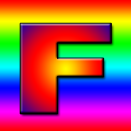
Fの文字が入ったテクスチャは、その向きをすぐに確認できるため、良いサンプルテクスチャであると一度教わりました。

-  const texture = device.createTexture({
-    label: 'yellow F on red',
-    size: [kTextureWidth, kTextureHeight],
-    format: 'rgba8unorm',
-    usage:
-      GPUTextureUsage.TEXTURE_BINDING |
-      GPUTextureUsage.COPY_DST,
-  });
+  const url = 'resources/images/f-texture.png';
+  const source = await loadImageBitmap(url);
+  const texture = device.createTexture({
+    label: url,
+    format: 'rgba8unorm',
+    size: [source.width, source.height],
+    usage: GPUTextureUsage.TEXTURE_BINDING |
+           GPUTextureUsage.COPY_DST |
+           GPUTextureUsage.RENDER_ATTACHMENT,
+  });
copyExternalImageToTextureでは、GPUTextureUsage.COPY_DSTとGPUTextureUsage.RENDER_ATTACHMENTの使用法フラグを含める必要があることに注意してください。
次に、ImageBitmapをテクスチャにコピーできます。
-  device.queue.writeTexture(
-      { texture },
-      textureData,
-      { bytesPerRow: kTextureWidth * 4 },
-      { width: kTextureWidth, height: kTextureHeight },
-  );
+  device.queue.copyExternalImageToTexture(
+    { source, flipY: true },
+    { texture },
+    { width: source.width, height: source.height },
+  );
copyExternalImageToTextureのパラメータは、ソース、宛先、サイズです。ソースについては、読み込み時にテクスチャを反転させたい場合はflipY: trueを指定できます。
そして、それは機能します!
GPUでミップを生成する
前の記事では、ミップマップも生成しましたが、その場合、画像データに簡単にアクセスできました。画像を読み込むときに、その画像を2Dキャンバスに描画し、getImageDataを呼び出してデータを取得し、最後にミップを生成してアップロードすることができました。これはかなり遅くなります。また、キャンバス2Dのレンダリング方法は意図的に実装に依存するため、損失が発生する可能性もあります。
ミップレベルを生成したとき、バイリニア補間を行いました。これは、GPUがminFilter: linearで行うこととまったく同じです。この機能を使用して、GPUでミップレベルを生成できます。
前の記事のmipmapFilterの例を変更して、画像を読み込み、GPUを使用してミップを生成するようにしましょう。
まず、テクスチャを作成するコードを変更して、ミップレベルを作成するようにします。作成する数を把握する必要があり、次のように計算できます。
  const numMipLevels = (...sizes) => {
    const maxSize = Math.max(...sizes);
    return 1 + Math.log2(maxSize) | 0;
  };
これを1つ以上の数値で呼び出すと、必要なミップの数が返されます。たとえば、numMipLevels(123, 456)は9を返します。
- レベル0:123、456
- レベル1:61、228
- レベル2:30、114
- レベル3:15、57
- レベル4:7、28
- レベル5:3、14
- レベル6:1、7
- レベル7:1、3
- レベル8:1、1
9ミップレベル
Math.log2は、数値を生成するために必要な2のべき乗を教えてくれます。つまり、Math.log2(8) = 3です。なぜなら、23 = 8だからです。同じことを別の言い方をすれば、Math.log2は、この数値を2で何回割ることができるかを教えてくれます。
Math.log2(8)
          8 / 2 = 4
                  4 / 2 = 2
                          2 / 2 = 1
したがって、8を2で3回割ることができます。これは、作成するミップレベルの数を計算するために必要なものです。Math.log2(largestSize) + 1です。1は、元のサイズのミップレベル0用です。
したがって、適切な数のミップレベルを作成できるようになりました。
  const texture = device.createTexture({
    label: url,
    format: 'rgba8unorm',
    mipLevelCount: numMipLevels(source.width, source.height),
    size: [source.width, source.height],
    usage: GPUTextureUsage.TEXTURE_BINDING |
           GPUTextureUsage.COPY_DST |
           GPUTextureUsage.RENDER_ATTACHMENT,
  });
  device.queue.copyExternalImageToTexture(
    { source, flipY: true, },
    { texture },
    { width: source.width, height: source.height },
  );
次のミップレベルを生成するには、これまで行ってきたように、既存のミップレベルから次のレベルに、minFilter: linearでテクスチャ付きクワッドを描画します。
コードは次のとおりです。
  const generateMips = (() => {
    let sampler;
    let module;
    const pipelineByFormat = {};

    return function generateMips(device, texture) {
      if (!module) {
        module = device.createShaderModule({
          label: 'textured quad shaders for mip level generation',
          code: /* wgsl */ `
            struct VSOutput {
              @builtin(position) position: vec4f,
              @location(0) texcoord: vec2f,
            };

            @vertex fn vs(
              @builtin(vertex_index) vertexIndex : u32
            ) -> VSOutput {
              let pos = array(
                // 1番目の三角形
                vec2f( 0.0,  0.0),  // 中央
                vec2f( 1.0,  0.0),  // 右、中央
                vec2f( 0.0,  1.0),  // 中央、上

                // 2番目の三角形
                vec2f( 0.0,  1.0),  // 中央、上
                vec2f( 1.0,  0.0),  // 右、中央
                vec2f( 1.0,  1.0),  // 右、上
              );

              var vsOutput: VSOutput;
              let xy = pos[vertexIndex];
              vsOutput.position = vec4f(xy * 2.0 - 1.0, 0.0, 1.0);
              vsOutput.texcoord = vec2f(xy.x, 1.0 - xy.y);
              return vsOutput;
            }

            @group(0) @binding(0) var ourSampler: sampler;
            @group(0) @binding(1) var ourTexture: texture_2d<f32>;

            @fragment fn fs(fsInput: VSOutput) -> @location(0) vec4f {
              return textureSample(ourTexture, ourSampler, fsInput.texcoord);
            }
          `,
        });

        sampler = device.createSampler({
          minFilter: 'linear',
        });
      }

      if (!pipelineByFormat[texture.format]) {
        pipelineByFormat[texture.format] = device.createRenderPipeline({
          label: 'mip level generator pipeline',
          layout: 'auto',
          vertex: {
            module,
          },
          fragment: {
            module,
            targets: [{ format: texture.format }],
          },
        });
      }
      const pipeline = pipelineByFormat[texture.format];

      const encoder = device.createCommandEncoder({
        label: 'mip gen encoder',
      });

      for (let baseMipLevel = 1; baseMipLevel < texture.mipLevelCount; ++baseMipLevel) {
        const bindGroup = device.createBindGroup({
          layout: pipeline.getBindGroupLayout(0),
          entries: [
            { binding: 0, resource: sampler },
            {
              binding: 1,
              resource: texture.createView({
                baseMipLevel: baseMipLevel - 1,
                mipLevelCount: 1,
              }),
            },
          ],
        });

        const renderPassDescriptor = {
          label: 'our basic canvas renderPass',
          colorAttachments: [
            {
              view: texture.createView({baseMipLevel, mipLevelCount: 1}),
              loadOp: 'clear',
              storeOp: 'store',
            },
          ],
        };

        const pass = encoder.beginRenderPass(renderPassDescriptor);
        pass.setPipeline(pipeline);
        pass.setBindGroup(0, bindGroup);
        pass.draw(6);  // call our vertex shader 6 times
        pass.end();
      }
      const commandBuffer = encoder.finish();
      device.queue.submit([commandBuffer]);
    };
  })();
上記のコードは長く見えますが、これまでのテクスチャの例で使用してきたコードとほぼ同じです。変更点
-
3つの変数を保持するクロージャを作成します。
module、sampler、pipelineByFormatです。moduleとsamplerについては、設定されていないかどうかを確認し、設定されていない場合は、将来保持して使用できるGPUSShaderModuleとGPUSamplerを作成します。 -
すべての例とほぼ同じシェーダーのペアがあります。唯一の違いはこの部分です。
-  vsOutput.position = uni.matrix * vec4f(xy, 0.0, 1.0);
-  vsOutput.texcoord = xy * vec2f(1, 50);
+  vsOutput.position = vec4f(xy * 2.0 - 1.0, 0.0, 1.0);
+  vsOutput.texcoord = vec2f(xy.x, 1.0 - xy.y);
シェーダーにあるハードコードされたクワッド位置データは0.0から1.0までなので、そのままでは、例で行ったように、描画しているテクスチャの右上4分の1しかカバーしません。領域全体をカバーする必要があるため、2を掛けて1を引くことで、-1、-1から+1、+1までのクワッドが得られます。
また、Yテクスチャ座標を反転させます。これは、テクスチャに描画するとき、+1、+1が右上にあるためですが、サンプリングしているテクスチャの右上がそこにあるようにしたいからです。サンプリングされたテクスチャの右上は+1、0です。
-
pipelineByFormatというオブジェクトがあり、これをテクスチャ形式へのパイプラインのマップとして使用します。これは、パイプラインが使用する形式を知る必要があるためです。 -
特定の形式のパイプラインがすでにあるかどうかを確認し、ない場合は作成します。
    if (!pipelineByFormat[texture.format]) {
      pipelineByFormat[texture.format] = device.createRenderPipeline({
        label: 'mip level generator pipeline',
        layout: 'auto',
        vertex: {
          module,
        },
        fragment: {
          module,
+          targets: [{ format: texture.format }],
        },
      });
    }
    const pipeline = pipelineByFormat[texture.format];
ここでの唯一の大きな違いは、
targetsがキャンバスにレンダリングするときに使用するpresentationFormatからではなく、テクスチャの形式から設定されることです。 -
最後に、
texture.createViewにいくつかのパラメータを使用します。生成する必要のある各ミップレベルをループします。データが含まれている最後のミップのバインドグループを作成し、現在のミップレベルに描画するようにrenderPassDescriptorを設定します。次に、その特定のミップレベルのrenderPassをエンコードします。完了すると、すべてのミップが入力されます。
    for (let baseMipLevel = 1; baseMipLevel < texture.mipLevelCount; ++baseMipLevel) {
      const bindGroup = device.createBindGroup({
        layout: pipeline.getBindGroupLayout(0),
        entries: [
          { binding: 0, resource: sampler },
+          {
+            binding: 1,
+            resource: texture.createView({
+              baseMipLevel: baseMipLevel - 1,
+              mipLevelCount: 1,
+            }),
+          },
        ],
      });

      const renderPassDescriptor = {
        label: 'our basic canvas renderPass',
        colorAttachments: [
          {
+            view: texture.createView({baseMipLevel, mipLevelCount: 1}),
            loadOp: 'clear',
            storeOp: 'store',
          },
        ],
      };

      const pass = encoder.beginRenderPass(renderPassDescriptor);
      pass.setPipeline(pipeline);
      pass.setBindGroup(0, bindGroup);
      pass.draw(6);  // call our vertex shader 6 times
      pass.end();
    }

    const commandBuffer = encoder.finish();
    device.queue.submit([commandBuffer]);
注:この関数は2Dテクスチャのみを処理します。キューブマップに関する記事では、この関数を拡張して2D配列テクスチャとキューブマップを処理する方法について説明しています。
単純な画像読み込み関数
画像をテクスチャに読み込み、ミップを生成するのを簡単にするためのサポート関数をいくつか作成しましょう。
これは、最初のミップレベルを更新し、オプションで画像を反転させる関数です。画像にミップレベルがある場合は、それらを生成します。
  function copySourceToTexture(device, texture, source, {flipY} = {}) {
    device.queue.copyExternalImageToTexture(
      { source, flipY, },
      { texture },
      { width: source.width, height: source.height },
    );

    if (texture.mipLevelCount > 1) {
      generateMips(device, texture);
    }
  }
これは、ソース(この場合はImageBitmap)が与えられた場合に、一致するサイズのテクスチャを作成し、前の関数を呼び出してデータで埋める関数です。
  function createTextureFromSource(device, source, options = {}) {
    const texture = device.createTexture({
      format: 'rgba8unorm',
*      mipLevelCount: options.mips ? numMipLevels(source.width, source.height) : 1,
      size: [source.width, source.height],
      usage: GPUTextureUsage.TEXTURE_BINDING |
             GPUTextureUsage.COPY_DST |
             GPUTextureUsage.RENDER_ATTACHMENT,
    });
    copySourceToTexture(device, texture, source, options);
    return texture;
  }
そして、これはURLが与えられた場合に、URLをImageBitmapとして読み込み、前の関数を呼び出してテクスチャを作成し、画像の内容で埋める関数です。
  async function createTextureFromImage(device, url, options) {
    const imgBitmap = await loadImageBitmap(url);
    return createTextureFromSource(device, imgBitmap, options);
  }
これらの設定で、mipmapFilterサンプルへの唯一の大きな変更はこれです。
-  const textures = [
-    createTextureWithMips(createBlendedMipmap(), 'blended'),
-    createTextureWithMips(createCheckedMipmap(), 'checker'),
-  ];
+  const textures = await Promise.all([
+    await createTextureFromImage(device,
+        'resources/images/f-texture.png', {mips: true, flipY: false}),
+    await createTextureFromImage(device,
+        'resources/images/coins.jpg', {mips: true}),
+    await createTextureFromImage(device,
+        'resources/images/Granite_paving_tileable_512x512.jpeg', {mips: true}),
+  ]);
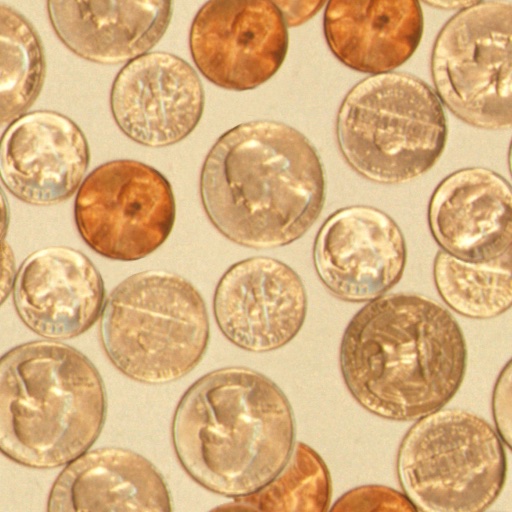
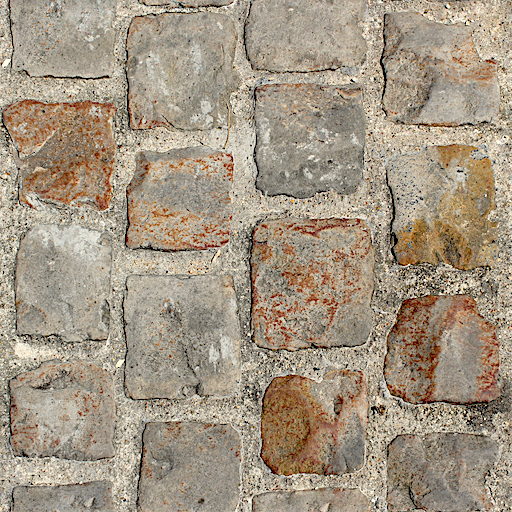
上記のコードは、上記のFテクスチャと、これらの2つのタイリングテクスチャを読み込みます。
そして、これがそれです。
キャンバスの読み込み
copyExternalImageToTextureは、他のソースを受け取ります。もう1つはHTMLCanvasElementです。これを使用して2Dキャンバスにものを描画し、その結果をWebGPUのテクスチャで取得できます。もちろん、WebGPUを使用してテクスチャに描画し、描画したばかりのテクスチャをレンダリングする他のもので使用できます。実際、ミップレベルにレンダリングし、そのミップレベルをテクスチャアタッチメントとして使用して次のミップレベルにレンダリングしたばかりです。
しかし、2Dキャンバスを使用すると、特定のことが簡単になる場合があります。2Dキャンバスには、比較的高レベルのAPIがあります。
では、まず何らかのキャンバスアニメーションを作成しましょう。
const size = 256;
const half = size / 2;

const ctx = document.createElement('canvas').getContext('2d');
ctx.canvas.width = size;
ctx.canvas.height = size;

const hsl = (h, s, l) => `hsl(${h * 360 | 0}, ${s * 100}%, ${l * 100 | 0}%)`;

function update2DCanvas(time) {
  time *= 0.0001;
  ctx.clearRect(0, 0, size, size);
  ctx.save();
  ctx.translate(half, half);
  const num = 20;
  for (let i = 0; i < num; ++i) {
    ctx.fillStyle = hsl(i / num * 0.2 + time * 0.1, 1, i % 2 * 0.5);
    ctx.fillRect(-half, -half, size, size);
    ctx.rotate(time * 0.5);
    ctx.scale(0.85, 0.85);
    ctx.translate(size / 16, 0);
  }
  ctx.restore();
}

function render(time) {
  update2DCanvas(time);
  requestAnimationFrame(render);
}
requestAnimationFrame(render);
そのキャンバスをWebGPUに読み込むには、前の例にいくつかの変更を加えるだけで済みます。
適切なサイズのテクスチャを作成する必要があります。最も簡単な方法は、上記で記述したのと同じコードを使用することです。
+  const texture = createTextureFromSource(device, ctx.canvas, {mips: true});

  const textures = await Promise.all([
-    await createTextureFromImage(device,
-        'resources/images/f-texture.png', {mips: true, flipY: false}),
-    await createTextureFromImage(device,
-        'resources/images/coins.jpg', {mips: true}),
-    await createTextureFromImage(device,
-        'resources/images/Granite_paving_tileable_512x512.jpeg', {mips: true}),
+    texture,
  ]);
次に、requestAnimationFrameループに切り替え、2Dキャンバスを更新し、WebGPUにアップロードする必要があります。
-  function render() {
+  function render(time) {
+    update2DCanvas(time);
+    copySourceToTexture(device, texture, ctx.canvas);

     ...


    requestAnimationFrame(render);
  }
  requestAnimationFrame(render);

  const observer = new ResizeObserver(entries => {
    for (const entry of entries) {
      const canvas = entry.target;
      const width = entry.contentBoxSize[0].inlineSize;
      const height = entry.contentBoxSize[0].blockSize;
      canvas.width = Math.max(1, Math.min(width, device.limits.maxTextureDimension2D));
      canvas.height = Math.max(1, Math.min(height, device.limits.maxTextureDimension2D));
-      render();
    }
  });
  observer.observe(canvas);

  canvas.addEventListener('click', () => {
    texNdx = (texNdx + 1) % textures.length;
-    render();
  });
これで、キャンバスをアップロードし、そのためのミップレベルを生成できます。
ビデオの読み込み
この方法でビデオを読み込むことは、何ら変わりありません。<video>要素を作成し、前の例でキャンバスに渡したのと同じ関数に渡すことができ、マイナーな調整で機能するはずです。
これがビデオです。
ImageBitmapとHTMLCanvasElementの幅と高さはwidthとheightプロパティですが、HTMLVideoElementの幅と高さはvideoWidthとvideoHeightにあります。したがって、その違いを処理するようにコードを更新しましょう。
+  function getSourceSize(source) {
+    return [
+      source.videoWidth || source.width,
+      source.videoHeight || source.height,
+    ];
+  }

  function copySourceToTexture(device, texture, source, {flipY} = {}) {
    device.queue.copyExternalImageToTexture(
      { source, flipY, },
      { texture },
-      { width: source.width, height: source.height },
+      getSourceSize(source),
    );

    if (texture.mipLevelCount > 1) {
      generateMips(device, texture);
    }
  }

  function createTextureFromSource(device, source, options = {}) {
+    const size = getSourceSize(source);
    const texture = device.createTexture({
      format: 'rgba8unorm',
-      mipLevelCount: options.mips ? numMipLevels(source.width, source.height) : 1,
-      size: [source.width, source.height],
+      mipLevelCount: options.mips ? numMipLevels(...size) : 1,
+      size,
      usage: GPUTextureUsage.TEXTURE_BINDING |
             GPUTextureUsage.COPY_DST |
             GPUTextureUsage.RENDER_ATTACHMENT,
    });
    copySourceToTexture(device, texture, source, options);
    return texture;
  }
では、ビデオ要素を設定しましょう。
  const video = document.createElement('video');
  video.muted = true;
  video.loop = true;
  video.preload = 'auto';
  video.src = 'resources/videos/Golden_retriever_swimming_the_doggy_paddle-360-no-audio.webm';

  const texture = createTextureFromSource(device, video, {mips: true});
そして、レンダリング時に更新します。
-  function render(time) {
-    update2DCanvas(time);
-    copySourceToTexture(device, texture, ctx.canvas);
+  function render() {
+    copySourceToTexture(device, texture, video);
ビデオの複雑な点の1つは、WebGPUに渡す前に再生が開始されるのを待つ必要があることです。最新のブラウザでは、video.requestVideoFrameCallbackを呼び出すことでこれを行うことができます。新しいフレームが利用可能になるたびに呼び出されるため、少なくとも1つのフレームが利用可能になったことを知るために使用できます。
フォールバックとして、時間が進むのを待って祈ることができます🙏。残念ながら、古いブラウザでは、ビデオを使用するのが安全な時期を知るのが難しいためです😅。
+  function startPlayingAndWaitForVideo(video) {
+    return new Promise((resolve, reject) => {
+      video.addEventListener('error', reject);
+      if ('requestVideoFrameCallback' in video) {
+        video.requestVideoFrameCallback(resolve);
+      } else {
+        const timeWatcher = () => {
+          if (video.currentTime > 0) {
+            resolve();
+          } else {
+            requestAnimationFrame(timeWatcher);
+          }
+        };
+        timeWatcher();
+      }
+      video.play().catch(reject);
+    });
+  }

  const video = document.createElement('video');
  video.muted = true;
  video.loop = true;
  video.preload = 'auto';
  video.src = 'resources/videos/Golden_retriever_swimming_the_doggy_paddle-360-no-audio.webm';
+  await startPlayingAndWaitForVideo(video);

  const texture = createTextureFromSource(device, video, {mips: true});
もう1つの複雑な点は、ビデオを開始する前にユーザーがページと対話するのを待つ必要があることです[1]。再生ボタン付きのHTMLを追加しましょう。
  <body>
    <canvas></canvas>
+    <div id="start">
+      <div>▶️</div>
+    </div>
  </body>
そして、それを中央に配置するためのCSSです。
#start {
  position: fixed;
  left: 0;
  top: 0;
  width: 100%;
  height: 100%;
  display: flex;
  justify-content: center;
  align-items: center;
}
#start>div {
  font-size: 200px;
  cursor: pointer;
}
次に、クリックされるのを待って非表示にする関数を記述しましょう。
+  function waitForClick() {
+    return new Promise(resolve => {
+      window.addEventListener(
+        'click',
+        () => {
+          document.querySelector('#start').style.display = 'none';
+          resolve();
+        },
+        { once: true });
+    });
+  }

  const video = document.createElement('video');
  video.muted = true;
  video.loop = true;
  video.preload = 'auto';
  video.src = 'resources/videos/Golden_retriever_swimming_the_doggy_paddle-360-no-audio.webm';
+  await waitForClick();
  await startPlayingAndWaitForVideo(video);

  const texture = createTextureFromSource(device, video, {mips: true});
ビデオを一時停止する待機も追加しましょう。
  const video = document.createElement('video');
  video.muted = true;
  video.loop = true;
  video.preload = 'auto';
  video.src = 'resources/videos/pexels-anna-bondarenko-5534310 (540p).mp4'; /* webgpufundamentals: url */
  await waitForClick();
  await startPlayingAndWaitForVideo(video);

+  canvas.addEventListener('click', () => {
+    if (video.paused) {
+      video.play();
+    } else {
+      video.pause();
+    }
+  });
そして、それでビデオをテクスチャで取得できるはずです。
1つの最適化として、ビデオが変更された場合にのみテクスチャを更新することができます。
例:
  const video = document.createElement('video');
  video.muted = true;
  video.loop = true;
  video.preload = 'auto';
  video.src = 'resources/videos/Golden_retriever_swimming_the_doggy_paddle-360-no-audio.webm';
  await waitForClick();
  await startPlayingAndWaitForVideo(video);

+  let alwaysUpdateVideo = !('requestVideoFrameCallback' in video);
+  let haveNewVideoFrame = false;
+  if (!alwaysUpdateVideo) {
+    function recordHaveNewFrame() {
+      haveNewVideoFrame = true;
+      video.requestVideoFrameCallback(recordHaveNewFrame);
+    }
+    video.requestVideoFrameCallback(recordHaveNewFrame);
+  }

  ...

  function render() {
+    if (alwaysUpdateVideo || haveNewVideoFrame) {
+      haveNewVideoFrame = false;
      copySourceToTexture(device, texture, video);
+    }

    ...
この変更により、新しいフレームごとにビデオのみを更新します。したがって、たとえば、表示レートが120フレーム/秒のデバイスでは、120フレーム/秒で描画するため、アニメーション、カメラの動きなどはスムーズになります。しかし、ビデオテクスチャ自体は、独自のフレームレート(たとえば30fps)でのみ更新されます。
しかし!WebGPUには、ビデオを効率的に使用するための特別なサポートがあります。
これについては、別の記事で説明します。上記の方法では、device.query.copyExternalImageToTextureを使用すると、実際にはコピーが作成されます。コピーには時間がかかります。たとえば、4Kビデオの解像度は通常3840×2160であり、rgba8unormの場合、フレームごとに31メガバイトのデータをコピーする必要があります。外部テクスチャを使用すると、ビデオのデータを直接使用できます(コピーなし)が、異なるメソッドが必要であり、いくつかの制限があります。
テクスチャアトラス
上記の例から、テクスチャで何かを描画するには、テクスチャを作成し、データを入れ、サンプラーでバインドグループにバインドし、シェーダーから参照する必要があることがわかります。では、オブジェクトに複数の異なるテクスチャを描画したい場合はどうすればよいでしょうか?脚と背もたれが木でできていて、クッションが布でできている椅子があったとします。
または、タイヤがゴムで、ボディが塗装で、バンパーとハブキャップがクロムの車です。
他に何もしなければ、椅子には2回描画する必要があると思うかもしれません。1回は木製のテクスチャで木材を描画し、もう1回は布製のテクスチャでクッションを描画します。車の場合は、タイヤ、ボディ、バンパーなど、いくつかの描画が必要になります。
すべてのオブジェクトに複数の描画呼び出しが必要になるため、これは遅くなります。シェーダーにさらに多くの入力(2、3、4つのテクスチャ)とそれぞれのテクスチャ座標を追加することで、これを修正しようとすることができますが、これはあまり柔軟ではなく、4つのテクスチャすべてを読み取り、それらの間で選択するコードを追加する必要があるため、遅くなります。
このケースをカバーする最も一般的な方法は、テクスチャアトラスと呼ばれるものを使用することです。テクスチャアトラスは、複数の画像を含むテクスチャの派手な名前です。次に、テクスチャ座標を使用して、どの部分がどこに行くかを選択します。
これらの6つの画像でキューブをラップしましょう。
 | 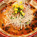 |
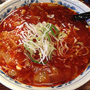 | 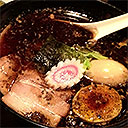 |
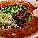 |  |
PhotoshopやPhotopeaなどの画像編集ソフトウェアを使用して、6つの画像をすべて1つの画像に入れることができます。
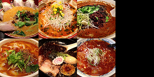
次に、キューブを作成し、画像の各部分をキューブの特定の面に選択するテクスチャ座標を提供します。簡単にするために、上記のテクスチャの6つの画像をすべて4x2の正方形に入れました。したがって、各正方形のテクスチャ座標を計算するのは非常に簡単なはずです。
上の図は、テクスチャ座標の0,0が左下隅であることがよく示唆されているため、紛らわしいかもしれません。しかし、実際には「下」はありません。テクスチャ座標0,0がテクスチャのデータの最初のピクセルを参照するという考え方だけです。テクスチャのデータの最初のピクセルは、画像の左上隅です。0,0 = 左下という考え方に従うと、テクスチャ座標は次のようになります。それらはまだ同じ座標です。
これは、キューブの位置頂点と、それらに付随するテクスチャ座標です。
function createCubeVertices() {
  const vertexData = new Float32Array([
     //  位置   |  テクスチャ座標
     //-------------+----------------------
     // 前面     左上の画像を選択
    -1,  1,  1,        0   , 0  ,
    -1, -1,  1,        0   , 0.5,
     1,  1,  1,        0.25, 0  ,
     1, -1,  1,        0.25, 0.5,
     // 右面     中央上の画像を選択
     1,  1, -1,        0.25, 0  ,
     1,  1,  1,        0.5 , 0  ,
     1, -1, -1,        0.25, 0.5,
     1, -1,  1,        0.5 , 0.5,
     // 背面      右上の画像を選択
     1,  1, -1,        0.5 , 0  ,
     1, -1, -1,        0.5 , 0.5,
    -1,  1, -1,        0.75, 0  ,
    -1, -1, -1,        0.75, 0.5,
    // 左面       左下の画像を選択
    -1,  1,  1,        0   , 0.5,
    -1,  1, -1,        0.25, 0.5,
    -1, -1,  1,        0   , 1  ,
    -1, -1, -1,        0.25, 1  ,
    // 底面     中央下の画像を選択
     1, -1,  1,        0.25, 0.5,
    -1, -1,  1,        0.5 , 0.5,
     1, -1, -1,        0.25, 1  ,
    -1, -1, -1,        0.5 , 1  ,
    // 上面        右下の画像を選択
    -1,  1,  1,        0.5 , 0.5,
     1,  1,  1,        0.75, 0.5,
    -1,  1, -1,        0.5 , 1  ,
     1,  1, -1,        0.75, 1  ,

  ]);

  const indexData = new Uint16Array([
     0,  1,  2,  2,  1,  3,  // 前
     4,  5,  6,  6,  5,  7,  // 右
     8,  9, 10, 10,  9, 11,  // 後
    12, 13, 14, 14, 13, 15,  // 左
    16, 17, 18, 18, 17, 19,  // 下
    20, 21, 22, 22, 21, 23,  // 上
  ]);

  return {
    vertexData,
    indexData,
    numVertices: indexData.length,
  };
}
この例を作成するには、カメラに関する記事の例から始める必要があります。まだ記事を読んでいない場合は、それを読んで、それが一部であるシリーズを読んで3Dを行う方法を学ぶことができます。今のところ、重要な部分は、上記で行ったように、頂点シェーダーから位置とテクスチャ座標を出力し、それらを使用してフラグメントシェーダーのテクスチャから値を検索することです。したがって、カメラの例のシェーダーに必要な変更を次に示します。上記を適用します。
struct Uniforms {
  matrix: mat4x4f,
};

struct Vertex {
  @location(0) position: vec4f,
-  @location(1) color: vec4f,
+  @location(1) texcoord: vec2f,
};

struct VSOutput {
  @builtin(position) position: vec4f,
-  @location(0) color: vec4f,
+  @location(0) texcoord: vec2f,
};

@group(0) @binding(0) var<uniform> uni: Uniforms;
+@group(0) @binding(1) var ourSampler: sampler;
+@group(0) @binding(2) var ourTexture: texture_2d<f32>;

@vertex fn vs(vert: Vertex) -> VSOutput {
  var vsOut: VSOutput;
  vsOut.position = uni.matrix * vert.position;
-  vsOut.color = vert.color;
+  vsOut.texcoord = vert.texcoord;
  return vsOut;
}

@fragment fn fs(vsOut: VSOutput) -> @location(0) vec4f {
-  return vsOut.color;
+  return textureSample(ourTexture, ourSampler, vsOut.texcoord);
}
行ったのは、頂点ごとの色から頂点ごとのテクスチャ座標に切り替え、そのテクスチャ座標をフラグメントシェーダーに渡すことだけです。上記で行ったようにです。次に、上記で行ったように、フラグメントシェーダーでそれを使用します。
JavaScriptでは、その例のパイプラインを、色を受け取るものからテクスチャ座標を受け取るものに変更する必要があります。
  const pipeline = device.createRenderPipeline({
    label: '2 attributes',
    layout: 'auto',
    vertex: {
      module,
      buffers: [
        {
-          arrayStride: (4) * 4, // (3) floats 4 bytes each + one 4 byte color
+          arrayStride: (3 + 2) * 4, // (3+2) floats 4 bytes each
          attributes: [
            {shaderLocation: 0, offset: 0, format: 'float32x3'},  // position
-            {shaderLocation: 1, offset: 12, format: 'unorm8x4'},  // color
+            {shaderLocation: 1, offset: 12, format: 'float32x2'},  // texcoord
          ],
        },
      ],
    },
    fragment: {
      module,
      targets: [{ format: presentationFormat }],
    },
    primitive: {
      cullMode: 'back',
    },
    depthStencil: {
      depthWriteEnabled: true,
      depthCompare: 'less',
      format: 'depth24plus',
    },
  });
データを小さく保つために、頂点バッファに関する記事で説明したようにインデックスを使用します。
-  const { vertexData, numVertices } = createFVertices();
+  const { vertexData, indexData, numVertices } = createCubeVertices();
  const vertexBuffer = device.createBuffer({
    label: 'vertex buffer vertices',
    size: vertexData.byteLength,
    usage: GPUBufferUsage.VERTEX | GPUBufferUsage.COPY_DST,
  });
  device.queue.writeBuffer(vertexBuffer, 0, vertexData);

+  const indexBuffer = device.createBuffer({
+    label: 'index buffer',
+    size: indexData.byteLength,
+    usage: GPUBufferUsage.INDEX | GPUBufferUsage.COPY_DST,
+  });
+  device.queue.writeBuffer(indexBuffer, 0, indexData);
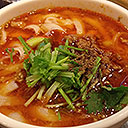
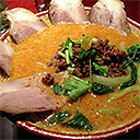
この例にテクスチャの読み込みとミップ生成のすべてのコードをコピーし、それを使用してテクスチャアトラス画像を読み込む必要があります。また、サンプラーを作成し、それらをバインドグループに追加する必要があります。
+  const texture = await createTextureFromImage(device,
+      'resources/images/noodles.jpg', {mips: true, flipY: false});
+
+  const sampler = device.createSampler({
+    magFilter: 'linear',
+    minFilter: 'linear',
+    mipmapFilter: 'linear',
+  });

  const bindGroup = device.createBindGroup({
    label: 'bind group for object',
    layout: pipeline.getBindGroupLayout(0),
    entries: [
      { binding: 0, resource: uniformBuffer },
+      { binding: 1, resource: sampler },
+      { binding: 2, resource: texture },
    ],
  });
3Dで描画するための行列を設定するために、いくつかの3D数学を行う必要があります。(繰り返しになりますが、3D数学の詳細については、カメラに関する記事を参照してください。)
  const degToRad = d => d * Math.PI / 180;

  const settings = {
    rotation: [degToRad(20), degToRad(25), degToRad(0)],
  };

  const radToDegOptions = { min: -360, max: 360, step: 1, converters: GUI.converters.radToDeg };

  const gui = new GUI();
  gui.onChange(render);
  gui.add(settings.rotation, '0', radToDegOptions).name('rotation.x');
  gui.add(settings.rotation, '1', radToDegOptions).name('rotation.y');
  gui.add(settings.rotation, '2', radToDegOptions).name('rotation.z');

  ...

  function render() {

    ...

    const aspect = canvas.clientWidth / canvas.clientHeight;
    mat4.perspective(
        60 * Math.PI / 180,
        aspect,
        0.1,      // zNear
        10,      // zFar
        matrixValue,
    );
    const view = mat4.lookAt(
      [0, 1, 5],  // camera position
      [0, 0, 0],  // target
      [0, 1, 0],  // up
    );
    mat4.multiply(matrixValue, view, matrixValue);
    mat4.rotateX(matrixValue, settings.rotation[0], matrixValue);
    mat4.rotateY(matrixValue, settings.rotation[1], matrixValue);
    mat4.rotateZ(matrixValue, settings.rotation[2], matrixValue);

    // upload the uniform values to the uniform buffer
    device.queue.writeBuffer(uniformBuffer, 0, uniformValues);
そして、レンダリング時にインデックスで描画する必要があります。
    const encoder = device.createCommandEncoder();
    const pass = encoder.beginRenderPass(renderPassDescriptor);
    pass.setPipeline(pipeline);
    pass.setVertexBuffer(0, vertexBuffer);
+    pass.setIndexBuffer(indexBuffer, 'uint16');

    ...

    pass.setBindGroup(0, bindGroup);
-    pass.draw(numVertices);
+    pass.drawIndexed(numVertices);

    pass.end();
そして、単一のテクスチャを使用して、各面に異なる画像を持つキューブが得られます。
テクスチャアトラスを使用すると、読み込むテクスチャが1つだけで、シェーダーは1つのテクスチャを参照するだけで済むため、単純なままであり、画像を別々に保持する場合のようにテクスチャごとに1回の描画呼び出しではなく、形状を描画するために1回の描画呼び出ししか必要としないため、優れています。
通常は音声なしで、ユーザーがページと対話するのを待たずにビデオを自動再生させるさまざまな方法があります。それらは時間とともに変化するようなので、ここでは解決策については説明しません。 ↩︎