WebGPU ポストプロセッシング - 基本的なCRTエフェクト
ポストプロセッシングとは、「オリジナル」の画像を作成した後に何らかの処理を行うことを意味します。ポストプロセッシングは、写真、ビデオ、2Dシーン、3Dシーンに適用できます。一般的には、画像があり、その画像に何らかのエフェクトを適用することを意味します。たとえば、Instagramでフィルターを選択するなどです。
このサイトのほとんどすべての例では、キャンバステクスチャにレンダリングしています。ポストプロセッシングを行うには、代わりに別のテクスチャにレンダリングします。次に、何らかの画像処理エフェクトを適用しながら、そのテクスチャをキャンバスにレンダリングします。
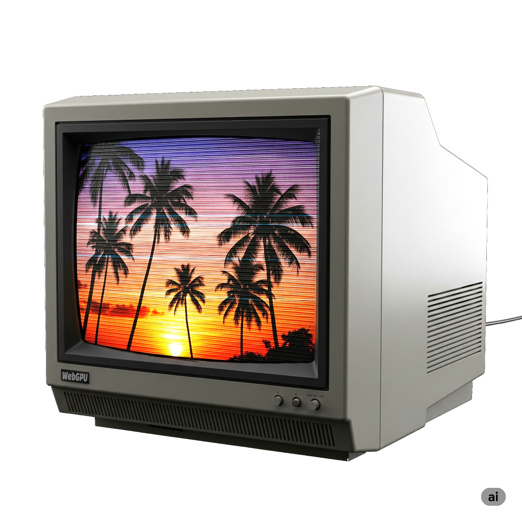
簡単な例として、1980年代のテレビのように見えるように、スキャンラインとCRT RGB要素を使用して画像を後処理してみましょう。
そのためには、タイミングに関する記事の冒頭のアニメーションの例を取り上げましょう。最初に行うことは、別のテクスチャにレンダリングし、そのテクスチャをキャンバスにレンダリングすることです。
これは、大きなクリップ空間の三角形を描画し、クリップ空間に収まる三角形の部分をカバーするテクスチャを描画できるように正しいUV座標を渡すシェーダーです。
  const postProcessModule = device.createShaderModule({
    code: /* wgsl */ `
      struct VSOutput {
        @builtin(position) position: vec4f,
        @location(0) texcoord: vec2f,
      };

      @vertex fn vs(
        @builtin(vertex_index) vertexIndex : u32,
      ) -> VSOutput {
        var pos = array(
          vec2f(-1.0, -1.0),
          vec2f(-1.0,  3.0),
          vec2f( 3.0, -1.0),
        );

        var vsOutput: VSOutput;
        let xy = pos[vertexIndex];
        vsOutput.position = vec4f(xy, 0.0, 1.0);
        vsOutput.texcoord = xy * vec2f(0.5, -0.5) + vec2f(0.5);
        return vsOutput;
      }

      @group(0) @binding(0) var postTexture2d: texture_2d<f32>;
      @group(0) @binding(1) var postSampler: sampler;

      @fragment fn fs2d(fsInput: VSOutput) -> @location(0) vec4f {
        let color = textureSample(postTexture2d, postSampler, fsInput.texcoord);
        return vec4f(color);
      }
    `,
  })
これは非常に単純で、テクスチャ付き画像の利用に関する記事でミップマップを生成するために使用したシェーダーと似ています。唯一の大きな違いは、元のシェーダーがクリップ空間をカバーするために2つの三角形を使用するのに対し、これは1つの大きな三角形を使用することです。
次に、これらのシェーダーを使用するには、パイプラインが必要です。
  const postProcessPipeline = device.createRenderPipeline({
    layout: 'auto',
    vertex: { module: postProcessModule },
    fragment: {
      module: postProcessModule,
      targets: [ { format: presentationFormat }],
    },
  });
このパイプラインはキャンバスにレンダリングするため、ターゲット形式を以前に検索したpresentationFormatとして設定する必要があります。
サンプラーとrenderPassDescriptorが必要です。
  const postProcessSampler = device.createSampler({
    minFilter: 'linear',
    magFilter: 'linear',
  });

  const postProcessRenderPassDescriptor = {
    label: 'post process render pass',
    colorAttachments: [
      { loadOp: 'clear', storeOp: 'store' },
    ],
  };
次に、元のrenderPassをキャンバスにレンダリングする代わりに、別のテクスチャにレンダリングする必要があります。
+  let renderTarget;
+
+  function setupPostProcess(canvasTexture) {
+    if (renderTarget?.width === canvasTexture.width &&
+        renderTarget?.height === canvasTexture.height) {
+      return;
+    }
+
+    renderTarget?.destroy();
+    renderTarget = device.createTexture({
+      size: canvasTexture,
+      format: 'rgba8unorm',
+      usage: GPUTextureUsage.RENDER_ATTACHMENT | GPUTextureUsage.TEXTURE_BINDING,
+    });
+    const renderTargetView = renderTarget.createView();
+    renderPassDescriptor.colorAttachments[0].view = renderTargetView;
+  }

  let then = 0;
  function render(now) {
    now *= 0.001;  // convert to seconds
    const deltaTime = now - then;
    then = now;

-    // Get the current texture from the canvas context and
-    // set it as the texture to render to.
-    renderPassDescriptor.colorAttachments[0].view =
-        context.getCurrentTexture().createView();
+    const canvasTexture = context.getCurrentTexture();
+    setupPostProcess(canvasTexture);

    ...
上記では、現在のcanvasTextureをsetupPostProcessに渡します。これにより、「renderTarget」テクスチャのサイズがキャンバスのサイズと同じかどうかがチェックされます。そうでない場合は、同じサイズの新しいテクスチャが作成されます。
次に、元のrenderPassDescriptorのカラーアタッチメントをこのrenderTargetテクスチャに設定します。
古いパイプラインはこのテクスチャにレンダリングするため、このテクスチャの形式に合わせて更新する必要があります。
  const pipeline = device.createRenderPipeline({
    label: 'per vertex color',
    layout: 'auto',
    vertex: {
      module,
      buffers: [
        ...
      ],
    },
    fragment: {
      module,
-      targets: [{ format: presentationFormat }],
+      targets: [{ format: 'rgba8unorm' }],
    },
  });
これらの変更だけでも、元のシーンをこのレンダーターゲットテクスチャにレンダリングし始めますが、キャンバスに何かを描画しないと何も表示されないため、それを行いましょう。
  function postProcess(encoder, srcTexture, dstTexture) {
    postProcessRenderPassDescriptor.colorAttachments[0].view = dstTexture.createView();
    const pass = encoder.beginRenderPass(postProcessRenderPassDescriptor);
    pass.setPipeline(postProcessPipeline);
    pass.setBindGroup(0, postProcessBindGroup);
    pass.draw(3);
    pass.end();
  }

  ...


  let then = 0;
  function render(now) {
    now *= 0.001;  // convert to seconds
    const deltaTime = now - then;
    then = now;

    const canvasTexture = context.getCurrentTexture();
    setupPostProcess(canvasTexture);

    const encoder = device.createCommandEncoder();
    const pass = encoder.beginRenderPass(renderPassDescriptor);

    ...

    pass.draw(numVertices, settings.numObjects);

    pass.end();

+    postProcess(encoder, renderTarget, canvasTexture);

    const commandBuffer = encoder.finish();
    device.queue.submit([commandBuffer]);

    requestAnimationFrame(render);
  }
  requestAnimationFrame(render);
もう1つだけ調整しましょう。オブジェクト数の設定はポストプロセッシングとは関係ないので、削除しましょう。
  const settings = {
-    numObjects: 100,
+    numObjects: 200,
  };

  const gui = new GUI();
-  gui.add(settings, 'numObjects', 0, kNumObjects, 1);
settings.numObjectsを完全に削除することもできましたが、いくつかの異なる場所で編集が必要になるため、今のところはそのままにしておきます。画像を埋めるために、数を200に設定します。
これを実行しても、元のものと目に見える違いはありません。
違いは、レンダーターゲットテクスチャにレンダリングし、そのテクスチャをキャンバスにレンダリングしていることです。これで、いくつかのエフェクトを適用し始めることができます。
古いCRTの最も明白な効果は、古いCRTには目に見えるスキャンラインがあることです。これは、画像が磁石を使用して画面全体に水平線のパターンでビームを向けることによって投影されたためです。
正弦波を使用して明暗のパターンを生成し、絶対値を取るだけで、同様の効果を得ることができます。


これをコードに追加しましょう。まず、この正弦波を適用するようにシェーダーを編集しましょう。
  const postProcessModule = device.createShaderModule({
    code: /* wgsl */ `
      struct VSOutput {
        @builtin(position) position: vec4f,
        @location(0) texcoord: vec2f,
      };

      @vertex fn vs(
        @builtin(vertex_index) vertexIndex : u32,
      ) -> VSOutput {
        var pos = array(
          vec2f(-1.0, -1.0),
          vec2f(-1.0,  3.0),
          vec2f( 3.0, -1.0),
        );

        var vsOutput: VSOutput;
        let xy = pos[vertexIndex];
        vsOutput.position = vec4f(xy, 0.0, 1.0);
        vsOutput.texcoord = xy * vec2f(0.5, -0.5) + vec2f(0.5);
        return vsOutput;
      }

+      struct Uniforms {
+        effectAmount: f32,
+        bandMult: f32,
+      };

      @group(0) @binding(0) var postTexture2d: texture_2d<f32>;
      @group(0) @binding(1) var postSampler: sampler;
+      @group(0) @binding(2) var<uniform> uni: Uniforms;

      @fragment fn fs2d(fsInput: VSOutput) -> @location(0) vec4f {
+        let banding = abs(sin(fsInput.position.y * uni.bandMult));
+        let effect = mix(1.0, banding, uni.effectAmount);

        let color = textureSample(postTexture2d, postSampler, fsInput.texcoord);
-        return vec4f(color);
+        return vec4f(color.rgb * effect, color.a);
      }
    `,
  });
正弦波は、書き込まれるピクセルのy座標であるfsInput.position.yに基づいています。つまり、0から始まる各スキャンラインに対して、0.5、1.5、2.5、3.5などになります。bendMultを使用すると、バンドのサイズを調整でき、effectAmountを使用すると、エフェクトをオン/オフにして、エフェクトとエフェクトなしを比較できます。
新しいシェーダーを使用するには、ユニフォームバッファを更新する必要があります。
  const postProcessUniformBuffer = device.createBuffer({
    size: 8,
    usage: GPUBufferUsage.UNIFORM | GPUBufferUsage.COPY_DST,
  });
バインドグループに追加する必要があります。
    postProcessBindGroup = device.createBindGroup({
      layout: postProcessPipeline.getBindGroupLayout(0),
      entries: [
        { binding: 0, resource: renderTargetView },
        { binding: 1, resource: postProcessSampler },
+        { binding: 2, resource: postProcessUniformBuffer },
      ],
    });
そして、いくつかの設定を追加する必要があります。
  const settings = {
    numObjects: 200,
+    affectAmount: 1,
+    bandMult: 1,
  };

  const gui = new GUI();
+  gui.add(settings, 'affectAmount', 0, 1);
+  gui.add(settings, 'bandMult', 0.01, 2.0);
そして、これらの設定をユニフォームバッファにアップロードする必要があります。
  function postProcess(encoder, srcTexture, dstTexture) {
+    device.queue.writeBuffer(
+      postProcessUniformBuffer,
+      0,
+      new Float32Array([
+        settings.affectAmount,
+        settings.bandMult,
+      ]),
+    );

    postProcessRenderPassDescriptor.colorAttachments[0].view = dstTexture.createView();
    const pass = encoder.beginRenderPass(postProcessRenderPassDescriptor);
    pass.setPipeline(postProcessPipeline);
    pass.setBindGroup(0, postProcessBindGroup);
    pass.draw(3);
    pass.end();
  }
そして、CRTのようなスキャンライン効果が得られます。
CRTは、LCDと同様に、画像を赤、緑、青の領域に分割します。CRTでは、これらの領域は今日のほとんどのLCDよりも一般的に大きかったため、これが目立つことがありました。その効果を近似するために何かを追加しましょう。
まず、シェーダーを変更しましょう。
  const postProcessModule = device.createShaderModule({
    code: /* wgsl */ `
      struct VSOutput {
        @builtin(position) position: vec4f,
        @location(0) texcoord: vec2f,
      };

      @vertex fn vs(
        @builtin(vertex_index) vertexIndex : u32,
      ) -> VSOutput {
        var pos = array(
          vec2f(-1.0, -1.0),
          vec2f(-1.0,  3.0),
          vec2f( 3.0, -1.0),
        );

        var vsOutput: VSOutput;
        let xy = pos[vertexIndex];
        vsOutput.position = vec4f(xy, 0.0, 1.0);
        vsOutput.texcoord = xy * vec2f(0.5, -0.5) + vec2f(0.5);
        return vsOutput;
      }

      struct Uniforms {
        effectAmount: f32,
        bandMult: f32,
+        cellMult: f32,
+        cellBright: f32,
      };

      @group(0) @binding(0) var postTexture2d: texture_2d<f32>;
      @group(0) @binding(1) var postSampler: sampler;
      @group(0) @binding(2) var<uniform> uni: Uniforms;

      @fragment fn fs2d(fsInput: VSOutput) -> @location(0) vec4f {
        let banding = abs(sin(fsInput.position.y * uni.bandMult));

+        let cellNdx = u32(fsInput.position.x * uni.cellMult) % 3;
+        var cellColor = vec3f(0);
+        cellColor[cellNdx] = 1;
+        let cMult = cellColors[cellNdx] + uni.cellBright;

-        let effect = mix(1.0, banding, uni.effectAmount);
+        let effect = mix(vec3f(1), banding * cMult, uni.effectAmount);
        let color = textureSample(postTexture2d, postSampler, fsInput.texcoord);
        return vec4f(color.rgb * effect, 1);
      }
    `,
  });
上記では、書き込まれるピクセルのx座標であるfsInput.position.xを使用しています。cellMultで乗算することで、セルサイズを選択できます。整数に変換し、3で割った余りを求めます。これにより、0、1、または2の数値が得られ、これを使用してcellColorの赤、緑、または青のチャネルを1に設定します。
調整としてcellBrightを追加し、古いバンディングと新しいエフェクトの両方を乗算します。effectはf32からvec3fに変更されたため、各チャネルに独立して影響を与えることができます。
JavaScriptに戻り、ユニフォームバッファのサイズを調整する必要があります。
  const postProcessUniformBuffer = device.createBuffer({
-    size: 8,
+    size: 16,
    usage: GPUBufferUsage.UNIFORM | GPUBufferUsage.COPY_DST,
  });
そして、GUIにいくつかの設定を追加します。
  const settings = {
    numObjects: 200,
    affectAmount: 1,
    bandMult: 1,
+    cellMult: 0.5,
+    cellBright: 1,
  };

  const gui = new GUI();
  gui.add(settings, 'affectAmount', 0, 1);
  gui.add(settings, 'bandMult', 0.01, 2.0);
+  gui.add(settings, 'cellMult', 0, 1);
+  gui.add(settings, 'cellBright', 0, 2);
そして、新しい設定をアップロードします。
  function postProcess(encoder, srcTexture, dstTexture) {
    device.queue.writeBuffer(
      postProcessUniformBuffer,
      0,
      new Float32Array([
        settings.affectAmount,
        settings.bandMult,
+        settings.cellMult,
+        settings.cellBright,
      ]),
    );

    postProcessRenderPassDescriptor.colorAttachments[0].view = dstTexture.createView();
    const pass = encoder.beginRenderPass(postProcessRenderPassDescriptor);
    pass.setPipeline(postProcessPipeline);
    pass.setBindGroup(0, postProcessBindGroup);
    pass.draw(3);
    pass.end();
  }
そして、CRTカラー要素のようなエフェクトが得られます。
上記のエフェクトは、CRTがどのように機能するかを完全に表現することを意図したものではありません。むしろ、CRTのように見えることを示唆し、うまくいけば理解しやすいことを意図していました。Web上でより凝ったテクニックを見つけることができます。
コンピュートシェーダーの使用
このためにコンピュートシェーダーを使用できるか、そして、おそらくもっと重要なことに、使用すべきかというトピックが浮上します。まず、「できるか」について説明しましょう。
ストレージテクスチャに関する記事で、コンピュートシェーダーを使用してテクスチャにレンダリングすることについて説明しました。
コードをコンピュートシェーダーを使用するように変換するには、キャンバステクスチャにSTORAGE_BINDINGの使用法を追加する必要があります。これは、前述の記事から、それをサポートするテクスチャ形式を確認して選択する必要があることを意味します。
async function main() {
  const adapter = await navigator.gpu?.requestAdapter();
+  const hasBGRA8UnormStorage = adapter?.features.has('bgra8unorm-storage');
-  const device = await adapter?.requestDevice();
+  const device = await adapter?.requestDevice({
+    requiredFeatures: [
+      ...(hasBGRA8UnormStorage ? ['bgra8unorm-storage'] : []),
+    ],
+  });
  if (!device) {
    fail('need a browser that supports WebGPU');
    return;
  }

  // Get a WebGPU context from the canvas and configure it
  const canvas = document.querySelector('canvas');
  const context = canvas.getContext('webgpu');
-  const presentationFormat = navigator.gpu.getPreferredCanvasFormat();
+  const presentationFormat = hasBGRA8UnormStorage
+    ? navigator.gpu.getPreferredCanvasFormat()
+    : 'rgab8unorm';
  context.configure({
    device,
    format: presentationFormat,
+    usage: GPUTextureUsage.RENDER_ATTACHMENT |
+           GPUTextureUsage.TEXTURE_BINDING |
+           GPUTextureUsage.STORAGE_BINDING,
  });
シェーダーをストレージテクスチャに書き込むように切り替える必要があります。
  const postProcessModule = device.createShaderModule({
    code: /* wgsl */ `
-      struct VSOutput {
-        @builtin(position) position: vec4f,
-        @location(0) texcoord: vec2f,
-      };
-
-      @vertex fn vs(
-        @builtin(vertex_index) vertexIndex : u32,
-      ) -> VSOutput {
-        var pos = array(
-          vec2f(-1.0, -1.0),
-          vec2f(-1.0,  3.0),
-          vec2f( 3.0, -1.0),
-        );
-
-        var vsOutput: VSOutput;
-        let xy = pos[vertexIndex];
-        vsOutput.position = vec4f(xy, 0.0, 1.0);
-        vsOutput.texcoord = xy * vec2f(0.5, -0.5) + vec2f(0.5);
-        return vsOutput;
-      }

      struct Uniforms {
        effectAmount: f32,
        bandMult: f32,
        cellMult: f32,
        cellBright: f32,
      };

      @group(0) @binding(0) var postTexture2d: texture_2d<f32>;
      @group(0) @binding(1) var postSampler: sampler;
      @group(0) @binding(2) var<uniform> uni: Uniforms;
+      @group(1) @binding(0) var outTexture: texture_storage_2d<${presentationFormat}, write>;

-      @fragment fn fs2d(fsInput: VSOutput) -> @location(0) vec4f {
-        let banding = abs(sin(fsInput.position.y * uni.bandMult));
-
-        let cellNdx = u32(fsInput.position.x * uni.cellMult) % 3;
+      @compute @workgroup_size(1) fn cs(@builtin(global_invocation_id) gid: vec3u) {
+        let outSize = textureDimensions(outTexture);
+        let banding = abs(sin(f32(gid.y) * uni.bandMult));
+
+        let cellNdx = u32(f32(gid.x) * uni.cellMult) % 3;
        var cellColor = vec3f(0);
        cellColor[cellNdx] = 1.0;
        let cMult = cellColor + uni.cellBright;

        let effect = mix(vec3f(1), banding * cMult, uni.effectAmount);
-        let color = textureSample(postTexture2d, postSampler, fsInput.texcoord);
-        return vec4f(color.rgb * effect, color.a);
+        let uv = (vec2f(gid.xy) + 0.5) / vec2f(outSize);
+        let color = textureSampleLevel(postTexture2d, postSampler, uv, 0);
+        textureStore(outTexture, gid.xy, vec4f(color.rgb * effect, color.a));
      }
    `,
  });
上記では、頂点シェーダーと関連部分を削除しました。また、書き込まれるピクセルの座標であったfsInput.positionもなくなりました。代わりに、コンピュートシェーダーの個々の呼び出しのglobal_invocation_idであるgidがあります。これをテクスチャ座標として使用します。これはvec3uなので、あちこちでキャストする必要があります。また、fsInput.texcoordもなくなりましたが、(vec2f(gid.xy) + 0.5) / vec2f(outSize)で同等のものを取得できます。
レンダーパスの使用をやめ、代わりにポストプロセッシングにコンピュートパスを使用する必要があります。
  const postProcessPipeline = device.createRenderPipeline({
    layout: 'auto',
-    vertex: { module: postProcessModule },
-    fragment: {
-      module: postProcessModule,
-      targets: [ { format: presentationFormat }],
-    },
+    compute: { module: postProcessModule },
  });

  function postProcess(encoder, srcTexture, dstTexture) {
    device.queue.writeBuffer(
      postProcessUniformBuffer,
      0,
      new Float32Array([
        settings.affectAmount,
        settings.bandMult,
        settings.cellMult,
        settings.cellBright,
      ]),
    );

+    const outBindGroup = device.createBindGroup({
+      layout: postProcessPipeline.getBindGroupLayout(1),
+      entries: [
+        { binding: 0, resource: dstTexture },
+      ],
+    });

-    postProcessRenderPassDescriptor.colorAttachments[0].view = dstTexture.createView();
-    const pass = encoder.beginRenderPass(postProcessRenderPassDescriptor);
+    const pass = encoder.beginComputePass();
    pass.setPipeline(postProcessPipeline);
    pass.setBindGroup(0, postProcessBindGroup);
-    pass.draw(3);
+    pass.dispatchWorkgroups(dstTexture.width, dstTexture.height);
    pass.end();
  }
それは機能します。
残念ながら、GPUによっては遅いです!コンピュートシェーダーの最適化に関する記事で、その理由の一部について説明しました。ワークグループサイズ1を使用すると簡単になりますが、遅くなります。
より大きなワークグループサイズを使用するように更新できます。これには、範囲外の場合はテクスチャへの書き込みをスキップする必要があります。
+  const workgroupSize = [16, 16];
  const postProcessModule = device.createShaderModule({
    code: /* wgsl */ `
      struct Uniforms {
        effectAmount: f32,
        bandMult: f32,
        cellMult: f32,
        cellBright: f32,
      };

      @group(0) @binding(0) var postTexture2d: texture_2d<f32>;
      @group(0) @binding(1) var postSampler: sampler;
      @group(0) @binding(2) var<uniform> uni: Uniforms;
      @group(1) @binding(0) var outTexture: texture_storage_2d<${presentationFormat}, write>;

-      @compute @workgroup_size(1) fn cs(@builtin(global_invocation_id) gid: vec3u) {
+      @compute @workgroup_size(${workgroupSize}) fn cs(@builtin(global_invocation_id) gid: vec3u) {
        let outSize = textureDimensions(outTexture);
+        if (gid.x >= outSize.x || gid.y >= outSize.y) {
+          return;
+        }
        let banding = abs(sin(f32(gid.y) * uni.bandMult));

        let cellNdx = u32(f32(gid.x) * uni.cellMult) % 3;
        var cellColor = vec3f(0);
        cellColor[cellNdx] = 1.0;
        let cMult = cellColor + uni.cellBright;

        let effect = mix(vec3f(1), banding * cMult, uni.effectAmount);
        let uv = (vec2f(gid.xy) + 0.5) / vec2f(outSize);
        let color = textureSampleLevel(postTexture2d, postSampler, uv, 0);
        textureStore(outTexture, gid.xy, vec4f(color.rgb * effect, color.a));
      }
    `,
  });
そして、より少ないワークグループをディスパッチする必要があります。
    const pass = encoder.beginComputePass();
    pass.setPipeline(postProcessPipeline);
    pass.setBindGroup(0, postProcessBindGroup);
    pass.setBindGroup(1, outBindGroup);
-    pass.dispatchWorkgroups(dstTexture.width, dstTexture.height);
+    pass.dispatchWorkgroups(
+      Math.ceil(dstTexture.width / workgroupSize[0]),
+      Math.ceil(dstTexture.height / workgroupSize[1]),
+    );
    pass.end();
これは機能します。
これははるかに高速です!しかし、残念ながら、一部のGPUでは、レンダーパスを使用するよりもまだ遅いです。
| GPU | コンピュートパス時間と レンダーパス時間 (高いほど悪い) |
|---|---|
| M1 Mac | 1x |
| AMD Radeon Pro 5300M | 1x |
| AMD Radeon Pro WX 32000 | 1.3x |
| Intel UHD Graphics 630 | 1.7x |
| NVidia 2070 Super | 2x |
それを高速化する方法については、この記事では大きすぎるトピックです。コンピュートシェーダーの最適化に関する記事を参照すると、同じルールが適用されます。残念ながら、この例にはどれもあまり関係ありません。実行しようとしているポストプロセッシングが共有ワークグループメモリから恩恵を受ける可能性がある場合は、コンピュートシェーダーを使用することが有益かもしれません。アクセスパターンも、GPUが多くのキャッシュミスを取得しないようにするために重要かもしれません。さらに別の方法は、サブグループを利用することです。
今のところ、さまざまな手法を試して、そのタイミングを確認することをお勧めします。または、実装しているアルゴリズムがワークグループやサブグループの共有データから本当に恩恵を受けることができる場合を除き、レンダーパスに固執します。GPUは、コンピュートシェーダーを実行するよりもはるかに長くテクスチャにレンダリングしてきたため、そのプロセスの多くのことが高度に最適化されています。